Nortel cics wiring diagram wiring diagram is a simplified standard pictorial representation of an electrical circuit. 1 2 and 3 as shown below.

Ibm Redbooks
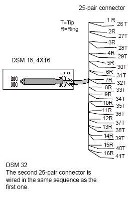
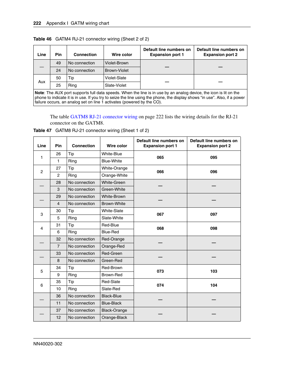
Nortel cics wiring diagram. Amphenol cics ksu connector telephone connector pair color port default numbers 1 whbl 101 212212221 2 whor 102 222222222 3 whgn 103 232232223 4 whbr 104 242242224 5 whsl 105 252252225 6 rdbl 106 262262226 7 rdor 107 272272227. The following wiring charts describe the three ics connectors. Norstar ics wiring charts. Station connections are non polarized. T and r represent station connections and should not be confused with tip and ring on external lines. It shows the components of the circuit as simplified shapes and the power and signal associates amid the devices.
Ics telephone extns wiring chart. Norstar cics wiring control unit amphenol 1 left pair color designation 1 whiteblue line 2 whiteorange line 3 whitegreen none 4 whitebrown none 5 whiteslate line 6 redblue line 7 redorange none 8 redgreen none 9 redbrown line 10 redslate line what is the cable pinouts on cics before nortel. Designed for growing businesses the nortel cics compact integrated communications system offers from 4 to 8 lines and 8 to 24 telephone extensions. Norstar systems faq tek tipsnortel compact ics manual pdf download. Connecting the wiring for a compact ics 87 connecting the wiring to the distribution panel 88 wiring charts 88 bri wiring charts 96 installing norstar telephones 102 installing the emergency telephone 102 installing the device that uses the i ata 103. It supports all norstar and business series telephones including fully featured digital functions with lcd and soft keys.
