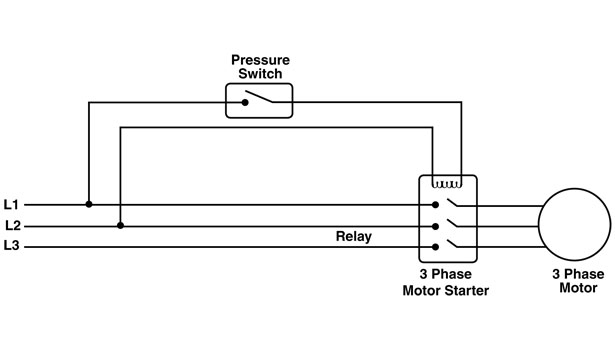
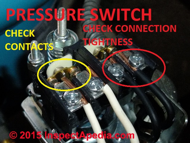
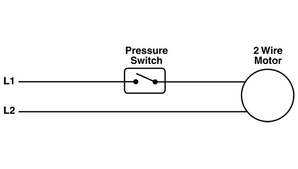
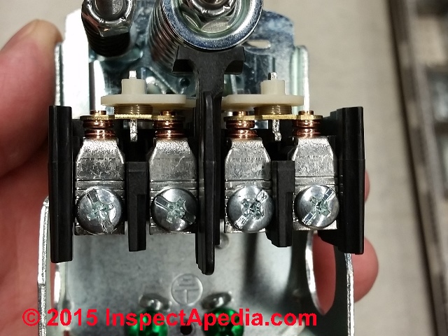
Wellborn variety of square d well pump pressure switch wiring diagram. Wellborn collection of well pump pressure switch wiring diagram.

Water Pump Pressure Switch Diagram General Wiring Diagram
Well pressure switch wiring diagram. It shows the elements of the circuit as streamlined shapes as well as the power and also signal links in between the tools. A wiring diagram usually gives info concerning the family member setting as well as plan of devices and terminals on the devices to assist in structure or servicing the gadget. It shows the components of the circuit as streamlined shapes and also the power and also signal links in between the devices. Collection of well pump pressure switch wiring diagram. It reveals the parts of the circuit as simplified forms and the power as well as signal connections between the tools. A wiring diagram is a simplified traditional photographic representation of an electric circuit.
A wiring diagram is a streamlined standard photographic representation of an electric circuit. Well pressure switch wiring diagram wiring diagram is a simplified agreeable pictorial representation of an electrical circuit. July 28 2018 by larry a. When the tank reaches its peak pressure typically at 60 pounds per square inch the switch cuts the electrical power to the water pump. As the tank is filled the water pressure increases within it. Put on safety glasses and test the wires at the well pressure switch with a voltmeter to confirm they have no voltage.
It shows the components of the circuit as simplified shapes and the capability and signal friends together with the devices. A wiring diagram is a streamlined traditional photographic representation of an electric circuit. Water pressure switches in well systems control the amount of water pumped to the systems storage tank. February 11 2019 by larry a. Place paper tape on the wires and label them feed from breaker box locate the wires coming from the pump or well put paper tape on them and mark as wires from pump or well.


