Wiring the i2c ina219 zero drift bidirectional currentpower monitor with mcu this is the ina219b breakout module to measure both high side voltage and dc current draw over i2c with 1 percent precision. Like usual i2c sensor can easily interfaced with arduino.
Ina219 Wiring
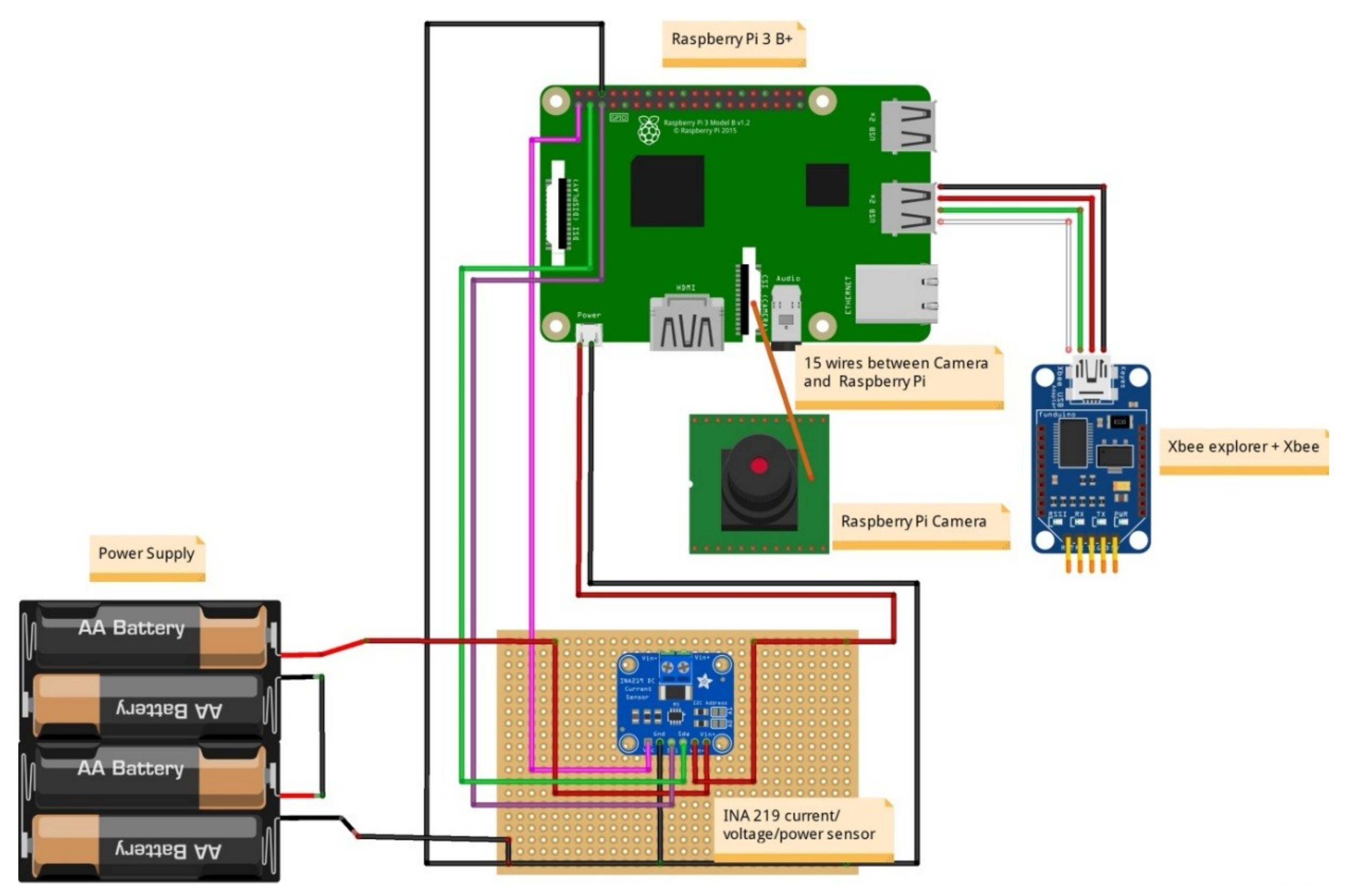
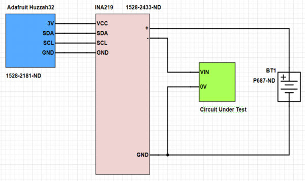
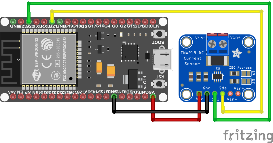
Ina219 wiring diagram. The device is readily available from the big name outlets. Including the pin outs. This chip uses i2c to communicate. Finally connect a wire from the negative terminal of the power supply to gnd. Each of the ina219 modules speak i2c to the rpi and the sdascl pins daisy chained with continuous jumpers back to the respective i2c pins on the rpi p3 and p5 to form an i2c bus. To install use the arduino library manager and search for adafruit ina219 and install the library.
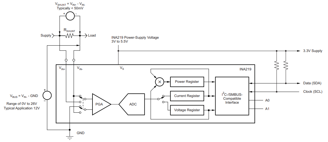
The dc current sensor used in this project is an ina219 high side dc current sensor breakout and the hall effect sensor used is an acs712 low current sensor board. Connect a wire from the ground line of the board to a 2. And there a load that connect to the sensor. Check out the links above for our tutorials and wiring diagrams. The image and table below detail some of module feature. Looking at the circuit diagram at the bottom of texas instruments 3.
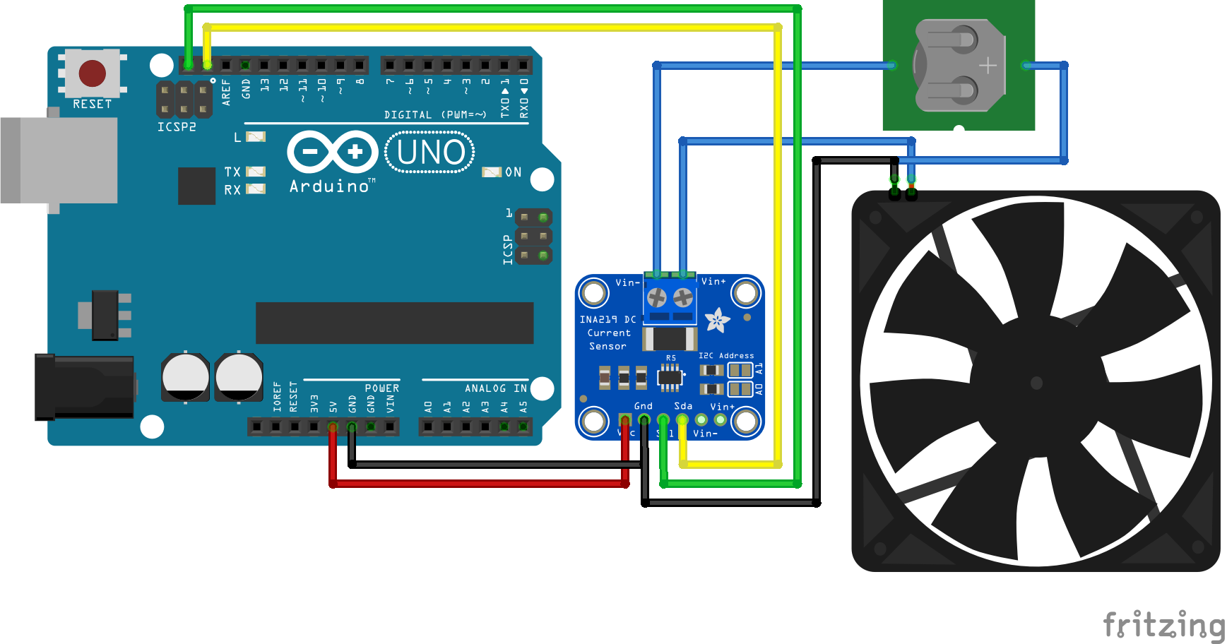
First wire up a ina219 to your board exactly as shown on the previous pages for arduino using an i2c interface. It uses 4 pins only. Ina219 current and voltage sensor module pin outs. In picture above that is the wiring diagram of ina219 and arduino. When using the common gnd i was reading voltages of about 615v. Adafruit has some excellent tutorials on wiring up and working with the ina219 which is where i got the majority of my information.
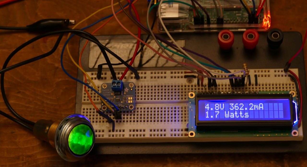
This allows the sensor to measure the load voltage as well as the load current. But the major difference is that using a common ground allowed me to read the voltage in real time as well. Otherwise i had to switch the contacts of the ina219 move the wire from vin to the ina219 gnd to read the voltage. Ina219 arduino current and voltage sensor tutorial get the necessary library. How to get an ina219 arduino module. The photo below shows an ina219 breakout board configured to measure the motor supply current on an adafruit motor shield.
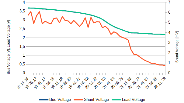
Whats interesting is the voltage values seem to differ. Wiring diagram ina219 breakout you will also need the ina breakout board which contains the inab chip that we will use to measure the here is the final schematic. Is it possible you could provide a simple diagram or breadboard example that includes h bridge and acs712. In addition connect some load to measure the current from in series to the sensors vin and vin pins as mentioned on the wiring page.






.png)
