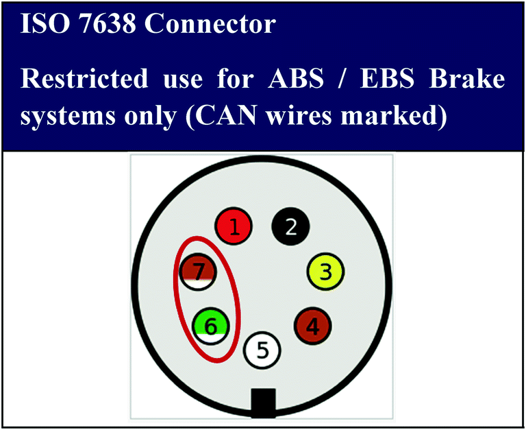
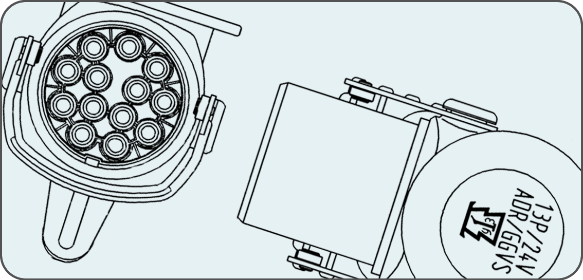
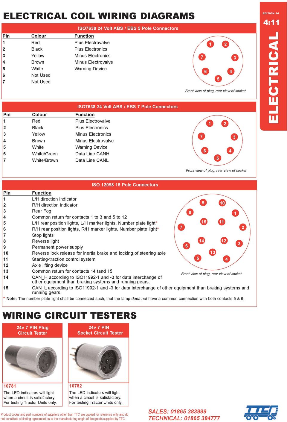
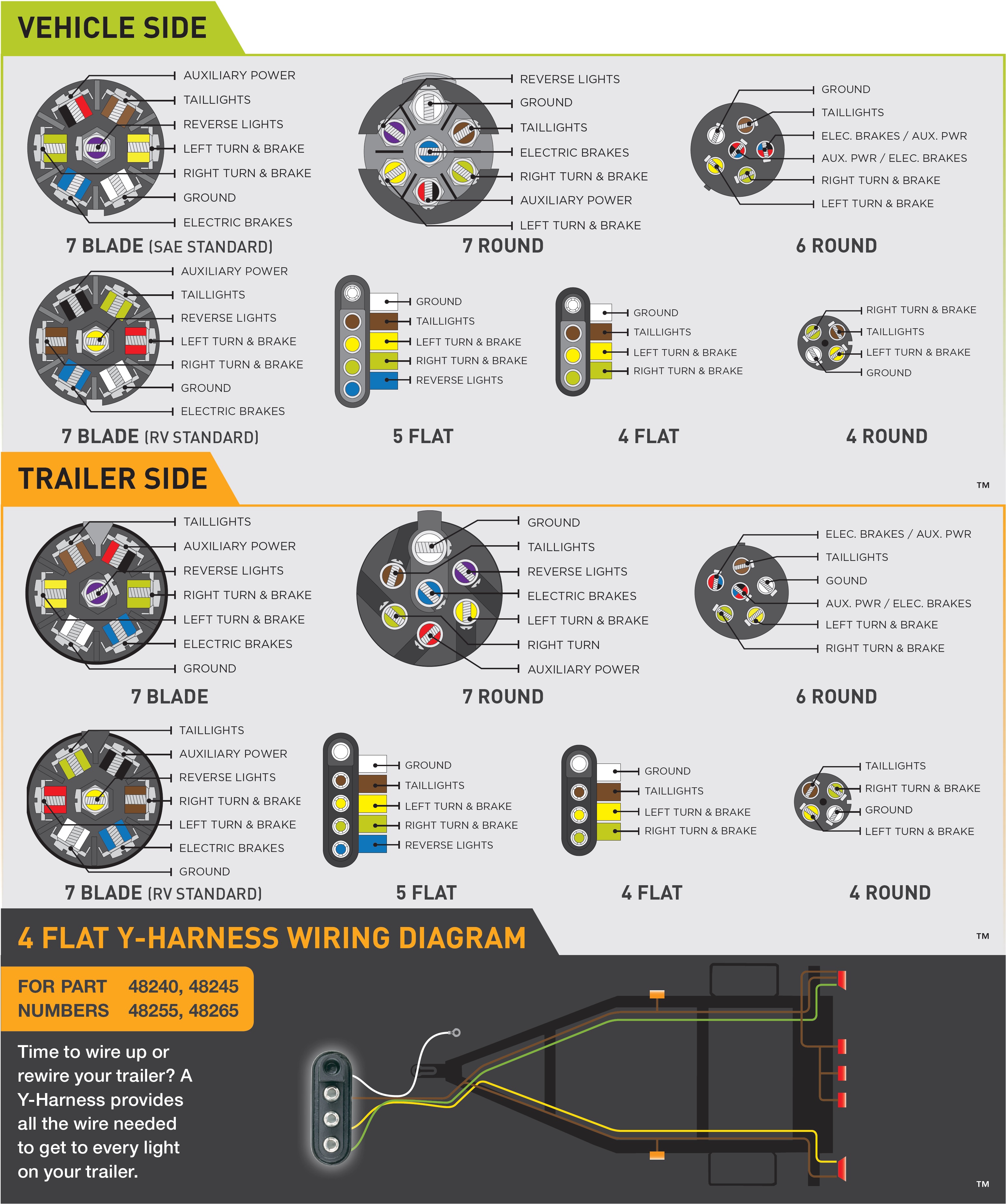
In which case you merely have to plug the dra07t into the. Rest of pins numbered clockwise or anti clockwise depending on view and whether plug or socket.

3e6 8 Pin Trailer Wiring Diagram Wiring Library
Ebs socket wiring diagram. 7 pin ebs trailer wiring diagram. Pin 1 is solid pin closest to key. 1 and 4 pins. Australia uses basically the same wiring with the exception for pin 5 and pin 2. An easy way to check the power from the iso socket is to use a multimeter and test between. Alternatively you could use an iso tester such as the drakefield dra07t to do all these tests for you.
The problematic part here is that pin 5 is used for trailer brake which means that if you for some reason connect an australian trailer to a towing vehicle with iso wiring you will get into trouble with the trailer brakes being applied as soon as you turn on the. A top of the range configuration delivers ebs braking with integrated abs electronic load sensing multiple can 3 modulator. Pin 7 is center pin. You should have three lives and two earths. 3 auxs fitted auxiliary equipment wiring colas ilas 45 steer axle lock auxiliary equipment wiring traction assist 46. 2 and 3 pins.
Eb gen3 premium is a 12 24v ebs with integrated roll over control intended for fitment to full semi and centre axle trailers using full air braking systems with air mechanical suspension. Wiring schematic 42 wiring diagram 2 sensor iso 7638 iso 1185 with 43 info centre 3 auxs fitted auxiliary equipment wiring 2 sensor iso 7638 44 iso 1185 with info centre and lws. Since january 1st 2015 all new trailers exceptions apply need to comply to adr3804 that specifies they have either anti lock brakes abs or an electronic brake system ebs to automatically adjust the brakes.


