Beka max wiring diagram wiring diagram is a simplified normal pictorial representation of an electrical circuit. It shows the components of the circuit as simplified shapes and the knack and signal friends surrounded by the devices.

1 Introduction Industrial Technical Manual Pages 201 250
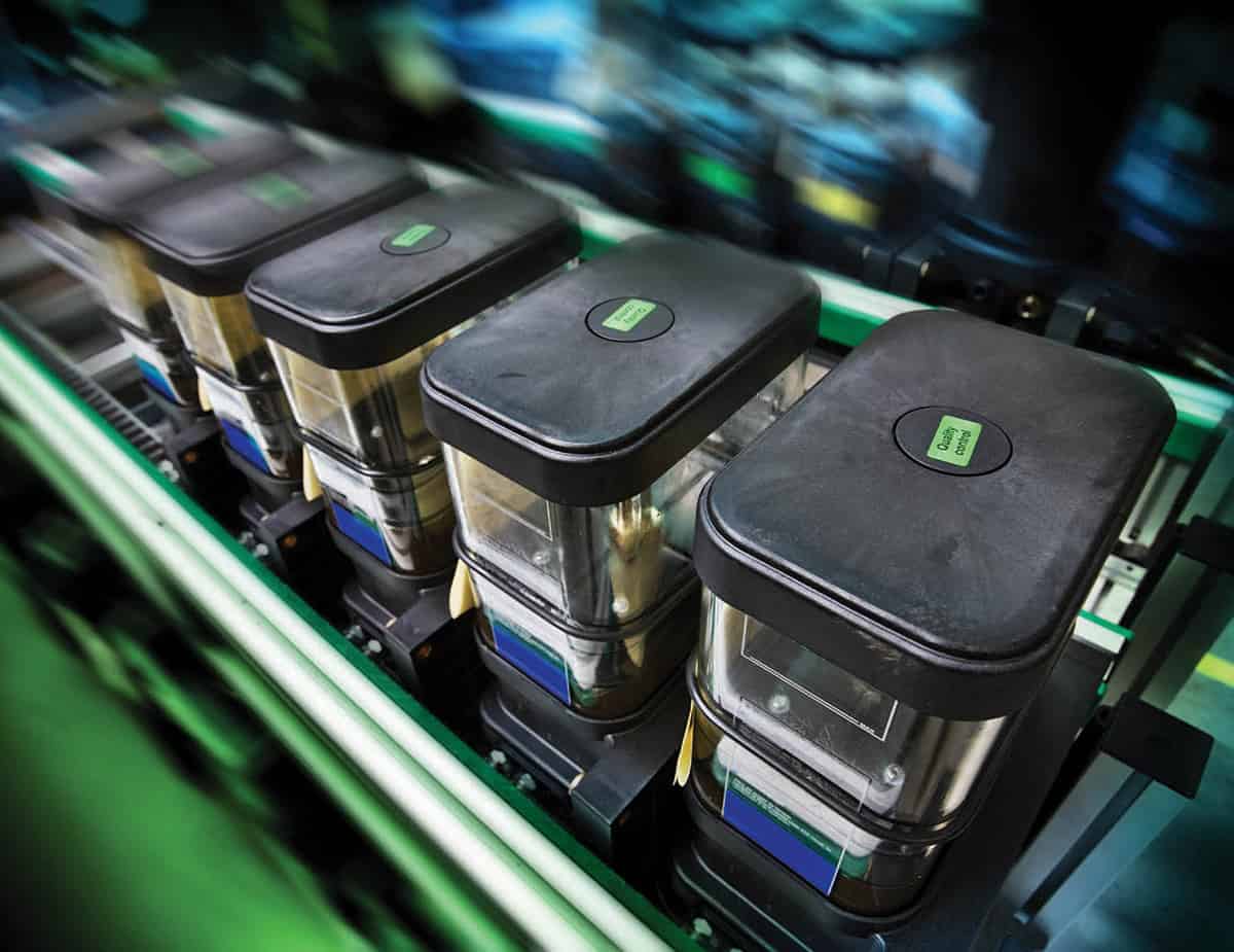
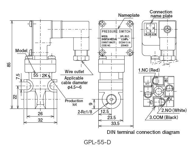
Beka max auto greaser wiring diagram. Our progressive systems are designed to handle standard shop grease. The beka max automatic lubrication system product range has been developed for the mobile and heavy equipment markets. 186 45 3 135 1 80 1 central lubrication pump technical data dimension plans terminal diagram pico. 38 a at 24 v dc max75aat12vdc. Automatic lubrication systems central lubrication. Bekaworld lp 258 sonwil drive buffalo ny 14225 usa tel.
8450 lawson road unit 5 milton on l9t 0j8 canada tel. Connection to existing signal transmitter e. 8450 lawson road unit 5 milton on l9t 0j8 canada tel. All products have been designed with the durability required for harsh environments found in trucking agriculture construction mining and other industries. 3 171 15 150 05 ca.
Gallery of Beka Max Auto Greaser Wiring Diagram