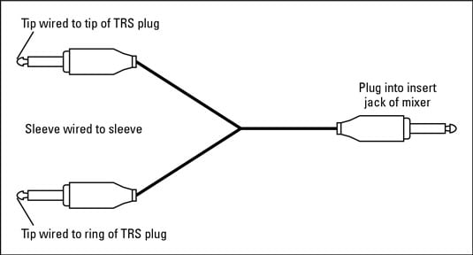
The three terminal 14 connector is commonly referred to as the trs or tip ring sleeve version. The trs connector can be used for many things including balanced audio sendreturn for insert points and leftright stereo just to name a few.

The Cable Connection Balanced And Unbalanced Iatse Local 695
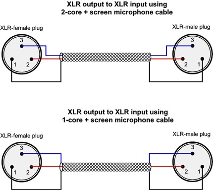
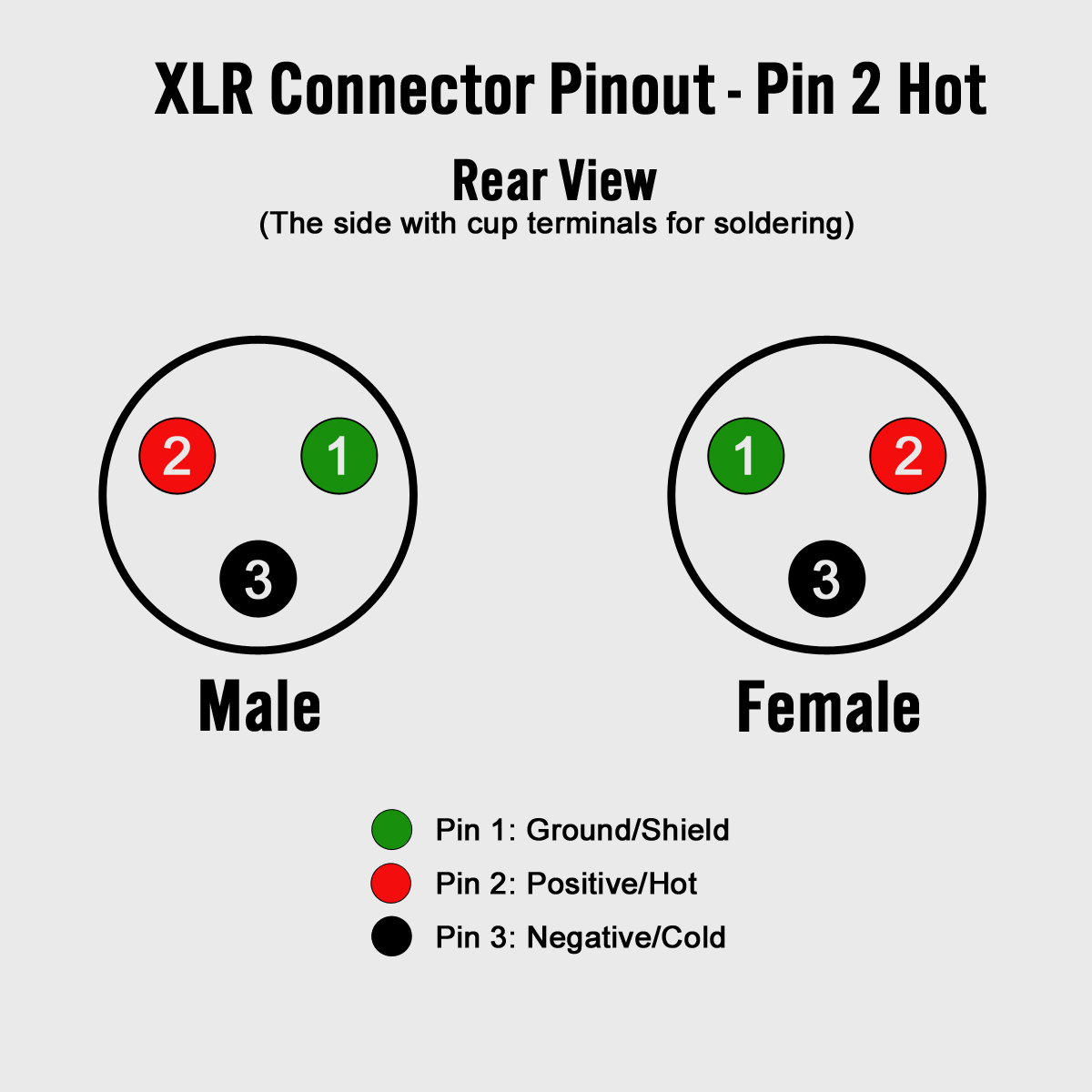
Xlr to 1 4 balanced wiring diagram. The rear view is the end you solder from here are the connections on each pin. Xlr to 14 mono plug. Collection of xlr to mono jack wiring diagram. The following is the aes industry standard for balanced audio xlr wiring commonly known as pin 2 hot. A wiring diagram is a simplified standard photographic depiction of an electric circuit. And if so can i get a copy.
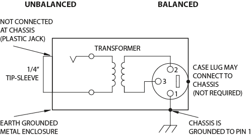
The ts connector is an unbalanced connector. Bueno in xlr category on nov 20 you can also find other images like wiring diagram parts diagram replacement parts electrical diagram repair manuals engine diagram engine scheme wiring harness fuse box vacuum diagram timing belt. Xlr pin 3 to 14 plug ring. Pinout diagram xlr 14 rca pinout diagram 18 trrs xlrf connector to mm jack trs stereobalanced mic cable. This can be done by either soldering the shield and negative wires of the xlr to the sleeve of the plug. 3 pin xlr wiring diagram cable wiring etc.
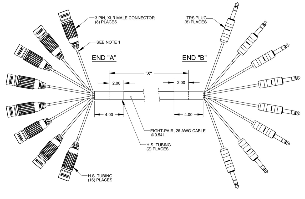
It reveals the components of the circuit as streamlined shapes and the power as well as signal links between the devices. Xlr to 14 trs connector wired for balanced mono the usual way to connect a 3 pin xlr to a 14 trs aka stereo jack plug is to use the following pin allocation. 1 4 inch jack wiring xlr to 14 trs connector wired for balanced mono the usual way to connect a 3 pin xlr to a 14 trs aka stereo jack plug is to use the following pin allocation. Xlr to ts 14 connecting a balanced xlr connector to. Xlr but the diagram for the balanced cable shows a 3 pin xlr. Xlr pin 1 to 14 plug sleeve.
From this it looks like the pins are bridged on the mini xlr end and. Xlr to 1 4 wiring diagram this is images about xlr to 1 4 wiring diagram posted by janell a. Xlr pin 2 to 14 plug tip. An explanation and diagram showing how to wire an xlr cannon connector to an rca connector. May 11 hello all i have just bought an enclosed 14 inch mono jack for a small amp cab i am building but it seems to have 3 connectors on itwiring. The above diagram shows you the pin numbering for both male and female xlr connectors from the front and the rear view.
3 pin xlr wiring standard. The most comon way to wire a 3 pin xlr to a 14 inch 65mm mono plug sometimes called a jack plug is to join the negative and shield together. This wiring configuration gives you a balanced mono audio cable. Xlr to 14 mono plug. Preamp tubes are rated in percentage of output. Balanced audio uses a cable made up of two conductors that are twisted.
3 pin xlr connectors are standard amongst line level and mic level audio applications. When connecting a 3 pin xlr to one rca you use the same wiring as if you were the rca. A wiring diagram is a streamlined conventional photographic depiction of an electric circuit. This produces an unbalanced audio cable. Normally the 3 pin xlr is connected to a 14 trs phono jack for balanced mono.
