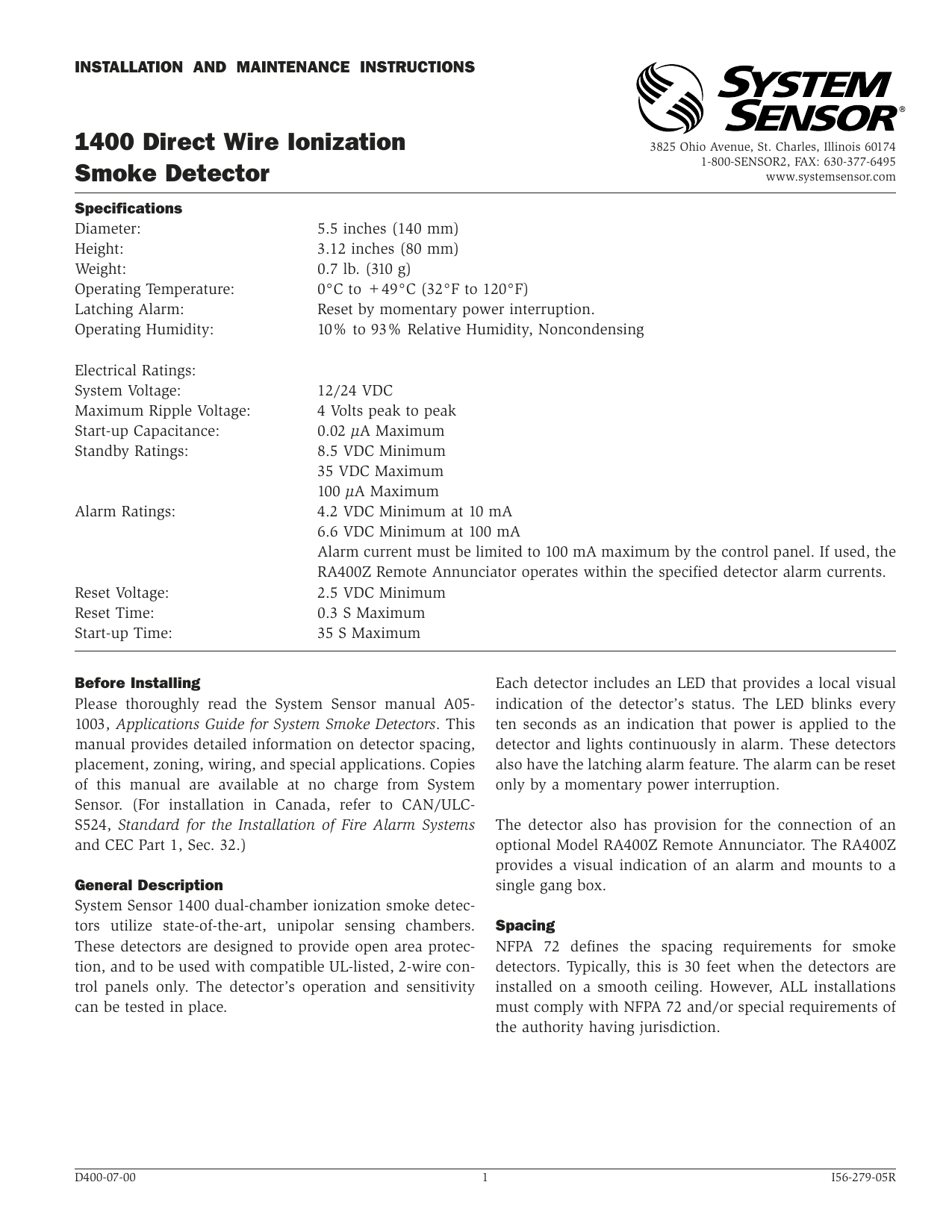
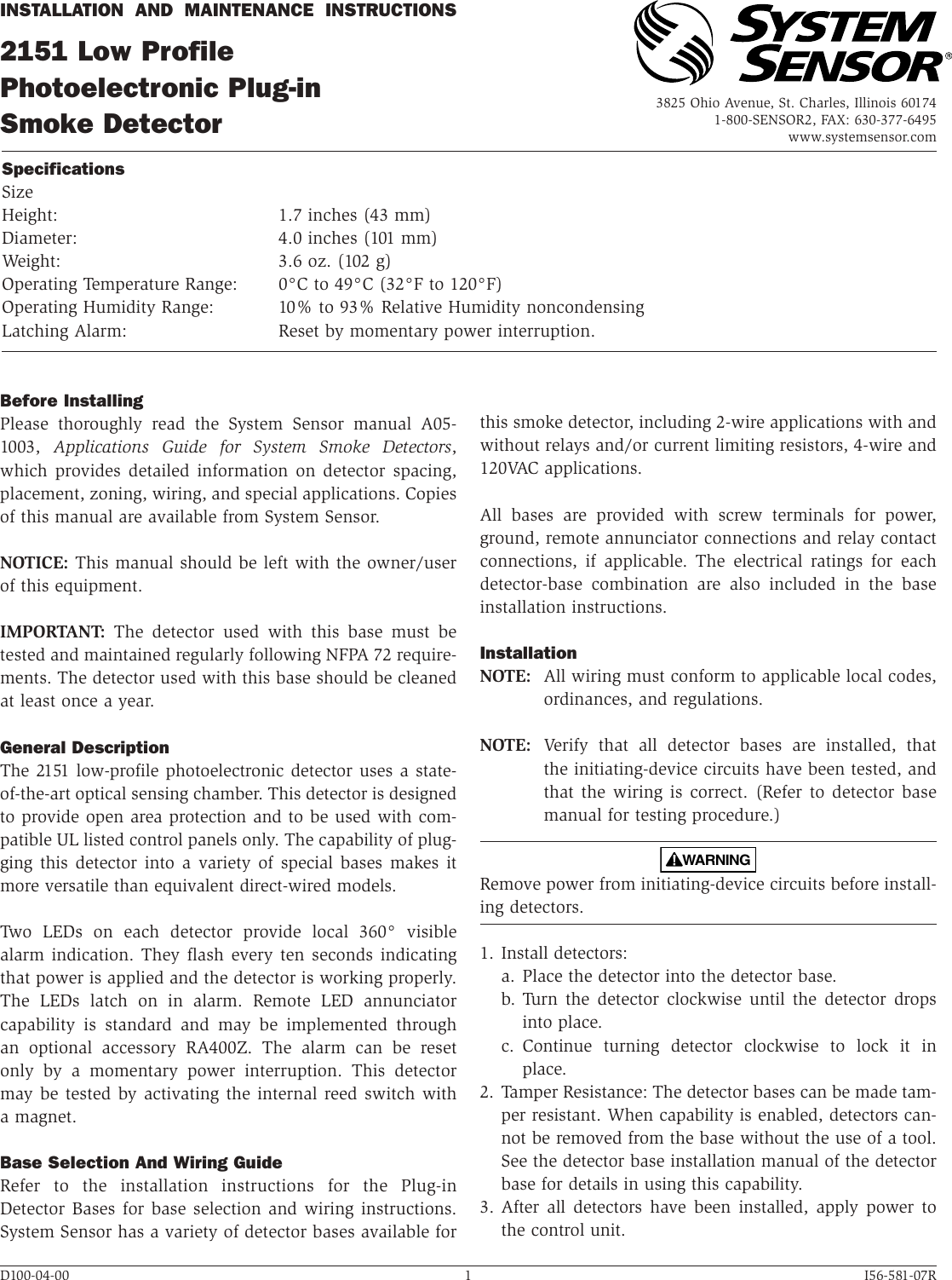
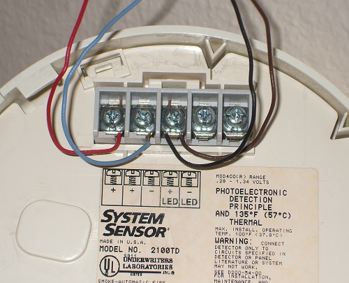
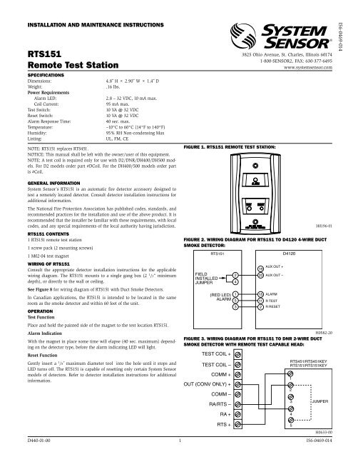
System sensor smoke detector wiring diagram. Assortment of system sensor smoke detector wiring diagram.
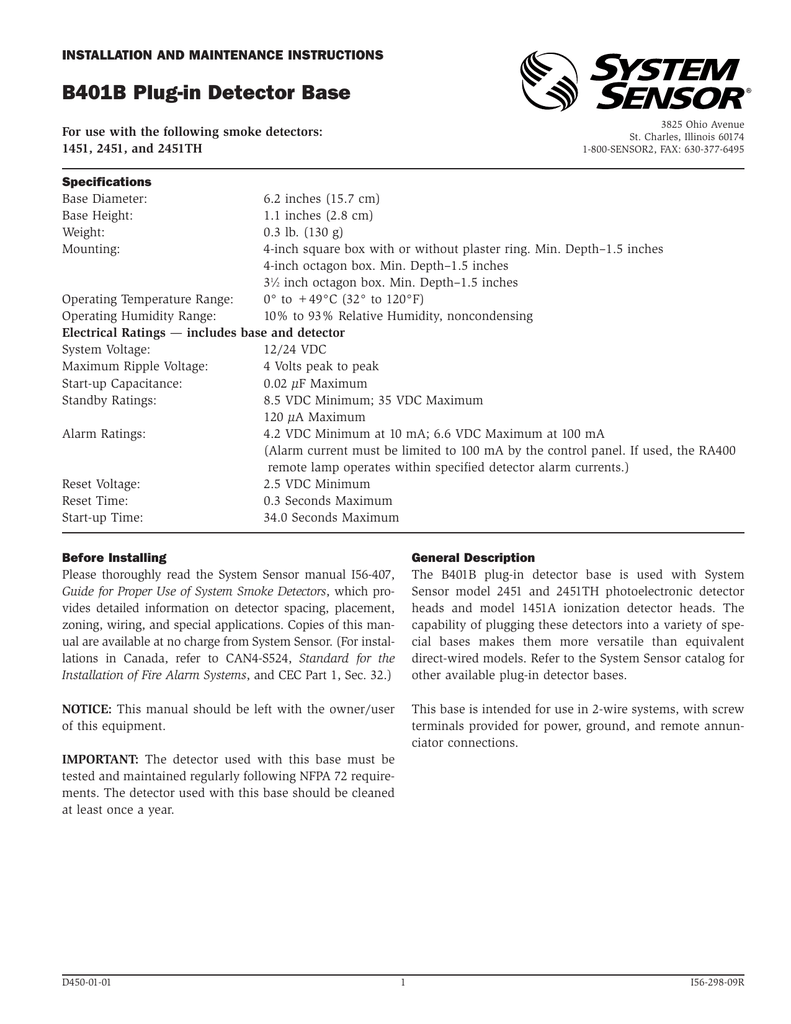
B401b Manual System Sensor Manualzz
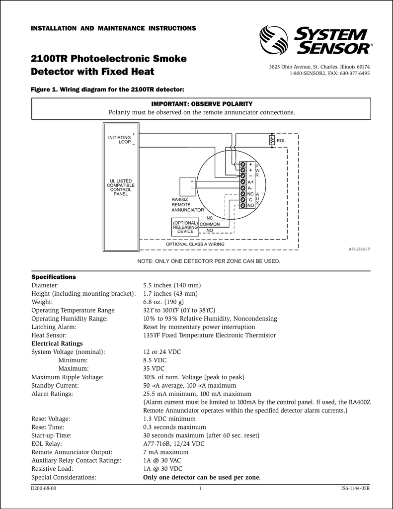
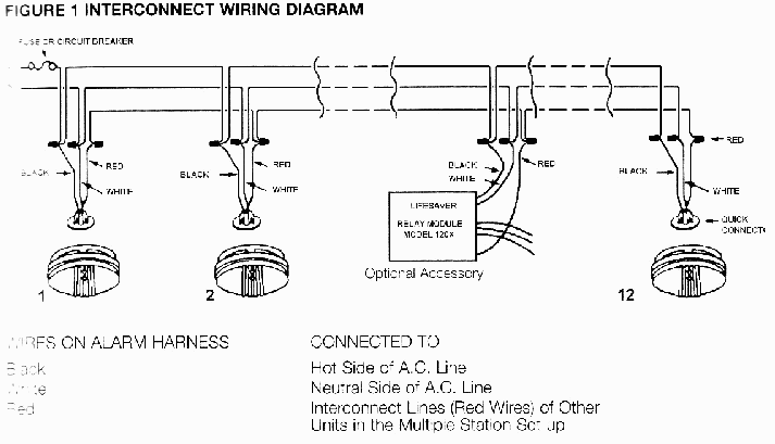
System sensor smoke detector wiring diagram. A wiring diagram is a simplified traditional pictorial depiction of an electric circuit. Wiring diagram for heating system new fire alarm wiring diagram best. It shows the elements of the circuit as simplified forms and the power as well as signal links in between the gadgets. The conductors used to connect smoke detectors to control panels and accessory. The main supply is 120v ac in us and 230v ac in eu. In our basic wiring diagram a single or multiple heat and smoke detectors are installed in the home by connecting the live line or hot neutral ground and an interconnected wire to the alarm.
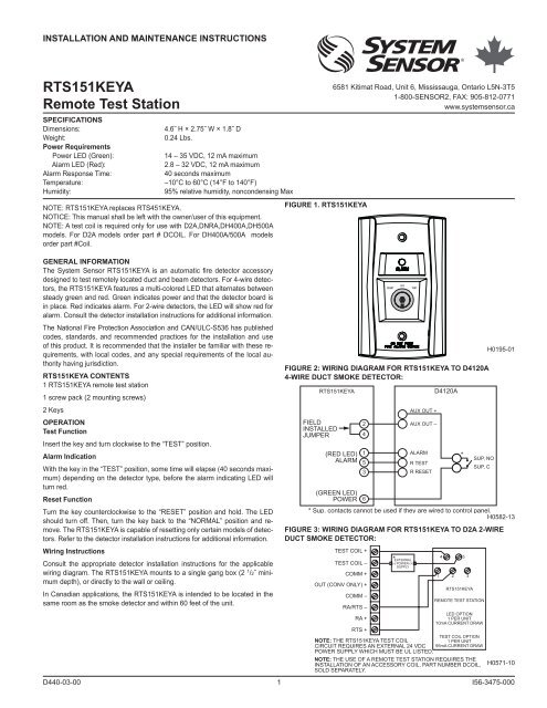
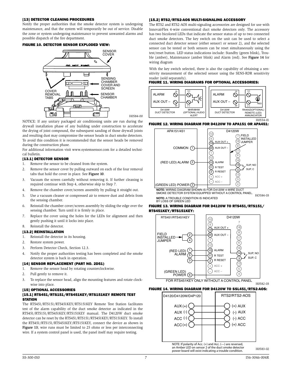
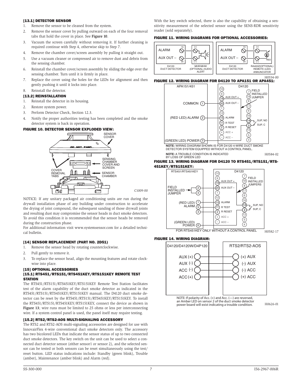
24 v ac 10 15 full w ave rectified unfil tered power ma y be used rts151rts151key optional remote test station magnet test switch alarm led red 4 5 2 1 ra rts ra test coil. This chart contains the current list of detectors and ul listed compatible control units. System sensor smoke detector wiring diagram collection system sensor d4120 wiring diagram. A smoke or heat detector can be installed to the existing or new home wiring. Truly we have been realized that how to wire smoke detectors in series diagram is being just about the most popular topic at this time. As identified by system sensors compatibility chart.
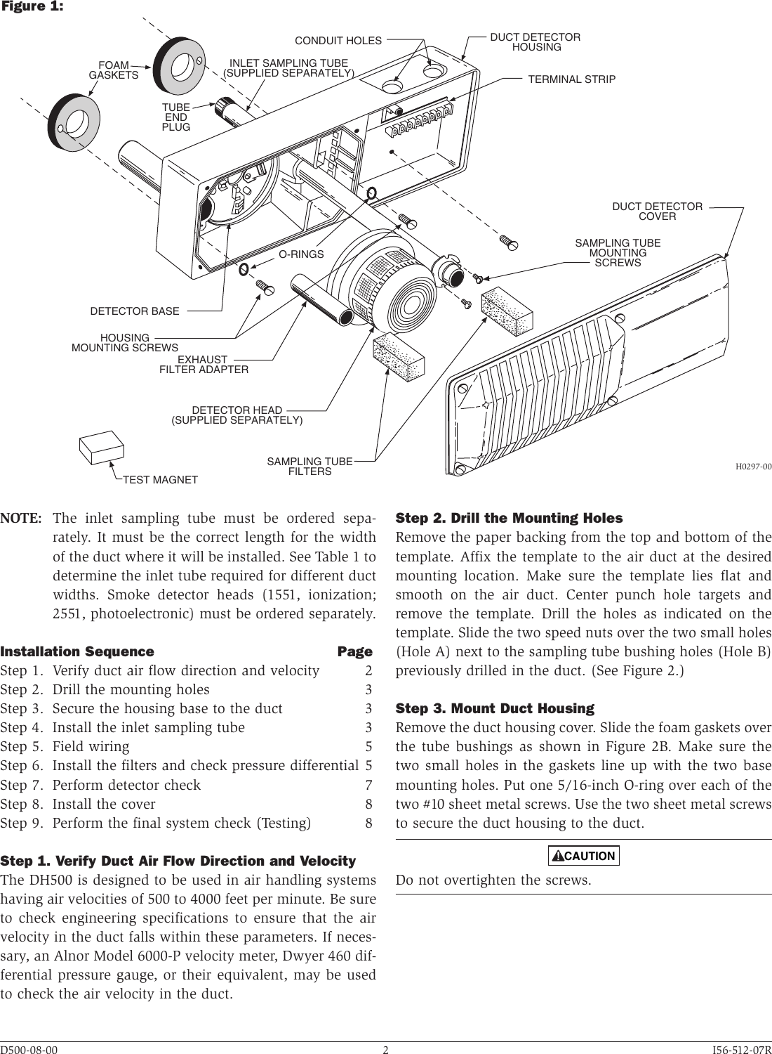
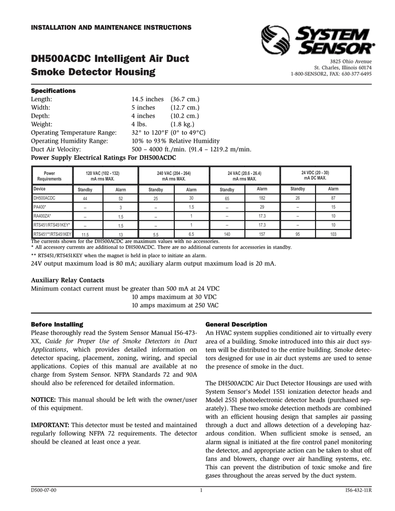
Nfpa standards 72 and 90a should also be refer enced for detailed information. Wiring diagram system sensor conventional smoke detector and. The air duct smoke detector shall be a system sensor innovairflex d4120 photoelectric duct smoke detector. A copy of this list is available from system sensor upon request. Wiring diagram 2w b and 2wt b 2 wire zone 2 wire control panel 2w b or 2wt b 5 ra 4 ra 3 inou t 2 ou t 1. Read system sensors applications guide for duct smoke detectors hvag53 which provides information on detector spacing placement zoning wiring and special applications.
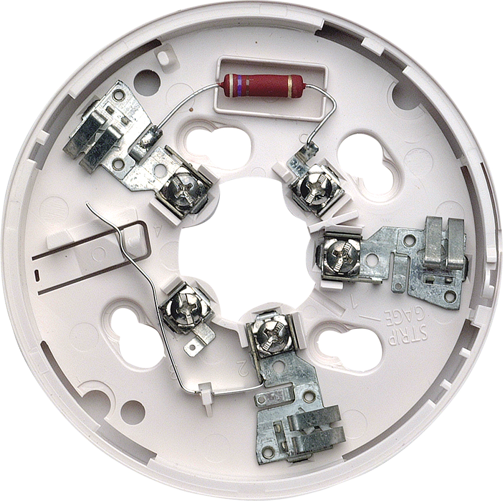
System sensor smoke detector wiring diagram a novice s guide to circuit diagrams. An initial appearance at a circuit representation could be confusing however if you could read a metro map you could read schematics. With the system sensor base and smoke detector being installed. The detector housing shall be ul listed per ul 268a specifically for use in air handling systems. Wiring diagrams figure 3a. All wiring must be installed in compliance with the national electrical code all applicable local codes and any special requirements of the authority having jurisdiction using the proper wire size.
How to install a hardwired smoke alarm ac power and alarm wiring intended for how to wire smoke detectors in series diagram image size 715 x 365 px. The flexible housing of the duct smoke detector fits multiple footprints from square to rectangular. Wiring for 2 wire duct smoke detector system wiring diagram for 2 wire duct smoke detectors powered from initiating device circuit. Hardwired smoke detectors system sensor alarm wiring.
