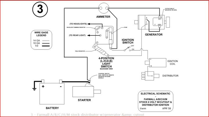
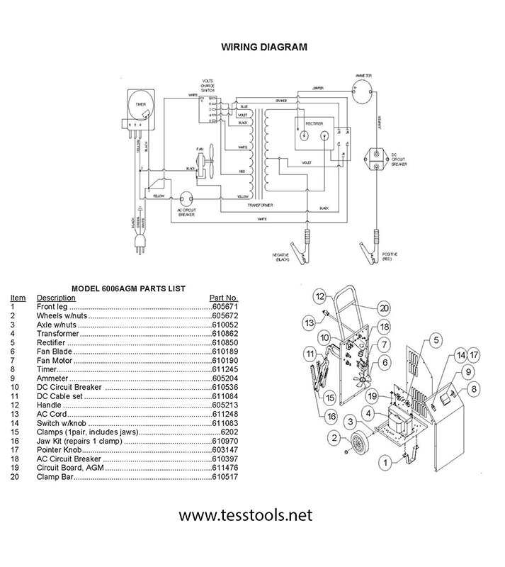
Of the alternator to the left terminal on the ammeter see wiring diagram. 3 phase to phase readings and off position for 3 phase 3 wire systems with or without pts.

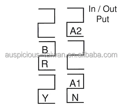
Victorshome Changeover Switch Lw28 20 3 Positions 8 Terminals Universal Rotary Cam Selector Latching Switches 550v 20a
Ammeter selector switch wiring diagram. Authorization a section circuit diagram. Cam operated rotary switches used to perform make and break the cam switches offers versatile mounting options in addition to standard. In this post i also write about voltmeter selector switch connection wiring but in the last time i talk and publish diagram about the 3 phase and in this post you will learn how to measure 3 phase 4 wire system voltage using a voltmeter selector switch. The most common switches are. 2 wire minimum with an insulation temperature rating of 220 f 105 c minimum from the battery. Moeller wiring manual 02 4 rotary switches and switch disconnectors.
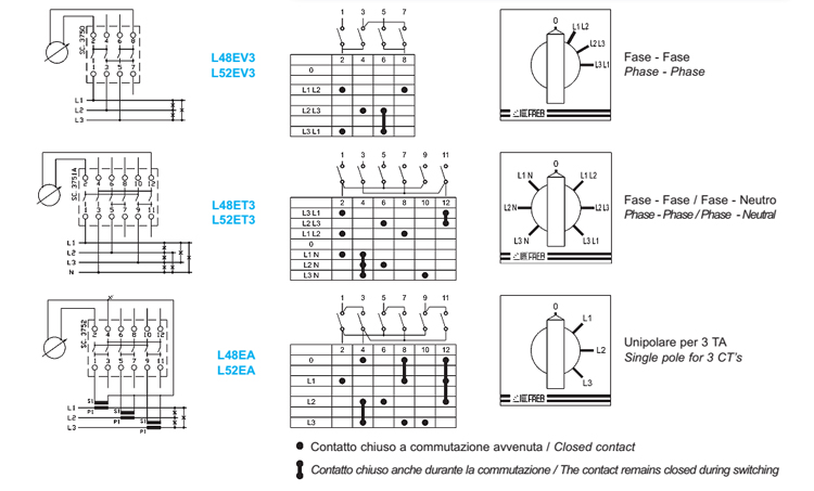
Schema di collegamento wiring diagram off rs st sy 3 fasi 3 3 phases 3 wires r s tn schema di collegamento wiring diagram tr st rsoffrn sn tn ys 11 3 phases. Ammeter selector switch wiring diagram wiring diagram is a simplified okay pictorial representation of an electrical circuit. Voltmeter and ammeter selector switches. Voltmeter selector switch wiring which was about the three phase voltage measuring and in which we did not talk about the neutral connection. Ammeter switches with 0 position start selector switches. Commutatori volt amperometrici.
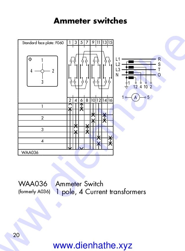
Apr 18 2018 a complete guide of ammeter selector switch wiring diagram with current transformers and ammeter. So come to the ammeter selector switch wiring diagram 3 days ago i am downloading and collecting some e book for him self and i find out a wiring connection diagram of amp selector switch in a e book pdf file which i highlight with text and make more easy to understand and you can see it below. How to connect voltage selector switch and ammeter selector switch wiring diagram. Capacitor bank testing procedure capacitor bank functioncapacitor bank wiring diagram duration. Pole change switches and reversing pole change switches page 363. It shows the components of the circuit as simplified shapes and the skill and signal connections amongst the devices.
Connect an 8 awg 100 mm. 3 phase current readings and off position for 3 phase 3 or 4 wire systems with 3 star connected cts. To be wired at end of ct circuitoff123.


