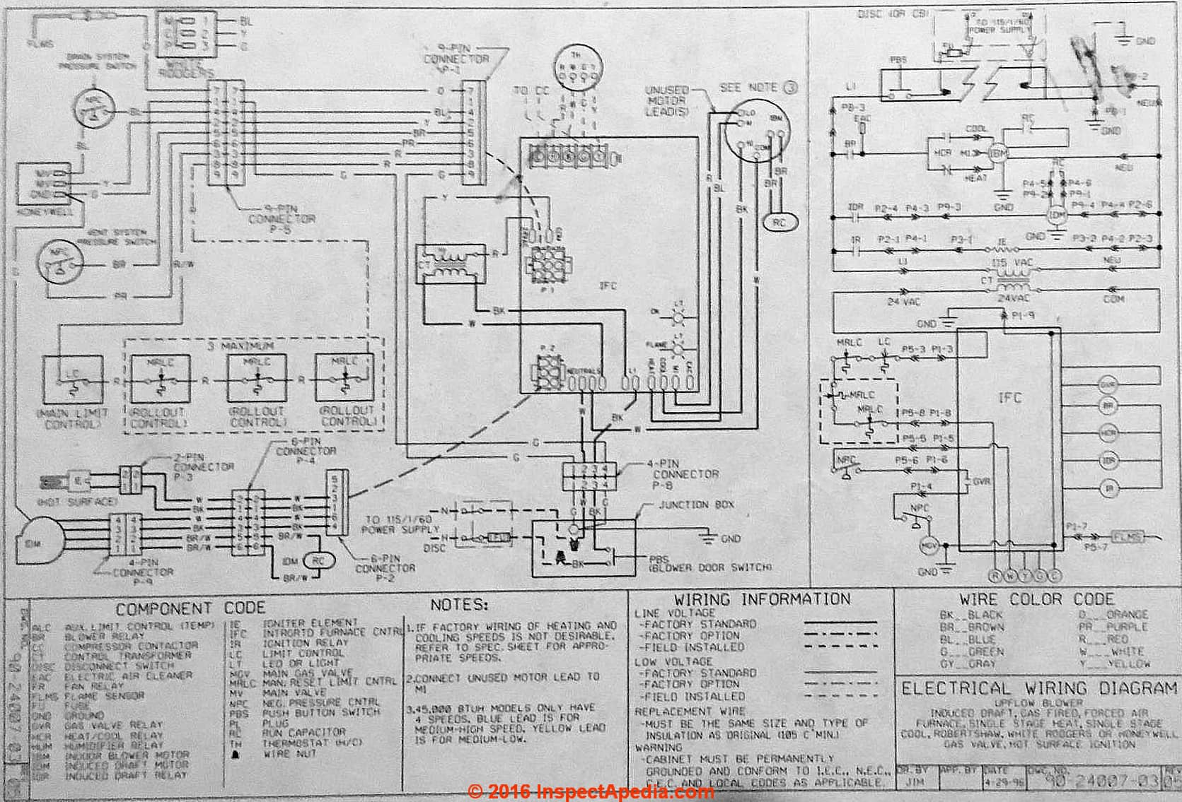
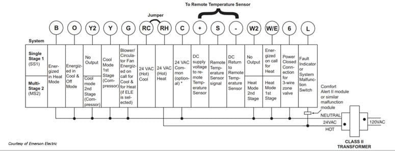
Moreover the heat source for a basic ac system can include heat strips for electric heat or even a hot water coil inside the. 31 the ladder diagram.
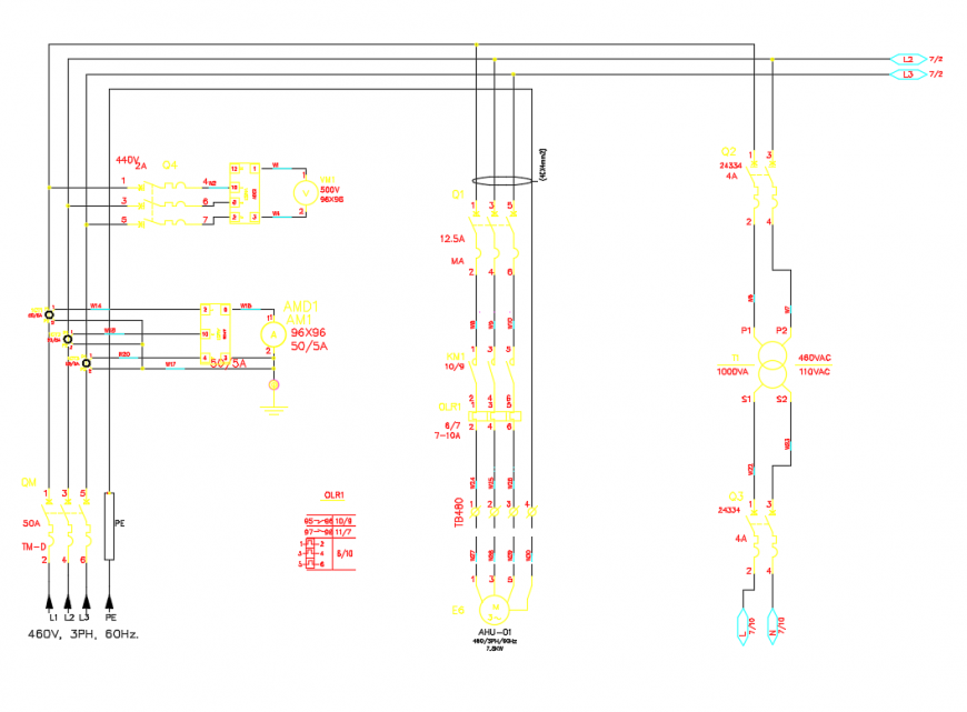
Control Wiring Diagram Of Dol Starter
Ahu wiring diagram. Replace single point wiring jumper bar if it is used on line side of breaker and tighten securely. There are three basic types of wiring diagrams used in the hvacr industry today which are. Double check wires and lugs to make sure all are secure and tight. It is the most common type of wiring diagrams. Ahu 1z wiring diagrams tdi conversions. Ahu controllerair handling unit controller ahu 11 the relay module is a self contained relay device that provides an interface between the low voltage circuitry and line voltage devices.
How to wire an air conditioner for control 5 wires the diagram below includes the typical control wiring for a conventional central air conditioning systemfurthermore it includes a thermostat a condenser and an air handler with a heat source. It is called ladder because the symbols that are used to represent the components in the system have been placed on. It reveals the parts of the circuit as simplified shapes and the power and signal links between the devices. Thermostat wiring diagrams heat pumps are wired for hvac control far differently than air conditioning systems so make sure you know the difference and correctly identify the type of hvac system you have installed. 8 air handling units fans and pumps 81 the field electrical wiring for other major components in central hvac system field power wiring for other major components in central hvac system like pumps fans and ahus are also a single point connection as in the case of chillers but we must use some type of motor starters orand variable. Install the rly in the desired location near the line voltage wiring in the upm.
A wiring diagram is a streamlined traditional pictorial representation of an electrical circuit. Position the rly002 so the terminal for relay contacts is adjacent to the. Additionally before you decide to change your thermostat make sure you have the correct tools especially a screwdriver and wire pliers. 8 horizontal right is the default factory configuration for the units. Ahu panel wiring diagram wiring diagram is a simplified enjoyable pictorial representation of an electrical circuitit shows the components of the circuit as simplified shapes and the facility and signal friends in the company of the devices. It shows the elements of the circuit as streamlined shapes and also the power and also signal connections in between the devices.
Assortment of rheem air handler wiring schematic. Check to make sure unit wiring to circuit breaker load lugs match that shown on the unit wiring diagram. The 96 and 97 use different wiring harnesses different glow plug relay circuits and a different ecu software program which requires different inputs and produces different outputs. The ladder diagram the line diagram the installation diagram. A wiring diagram is a streamlined standard photographic depiction of an electrical circuit. Variety of goodman aruf air handler wiring diagram.





/Page-1270005.png)

