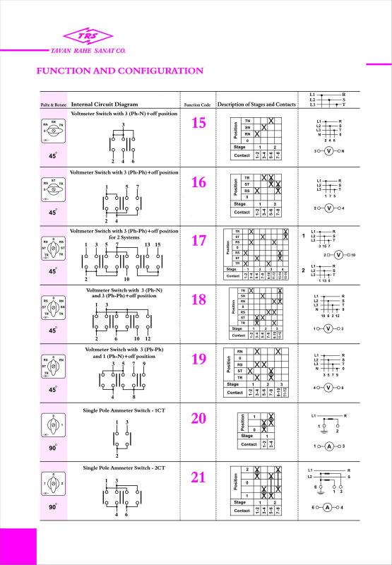
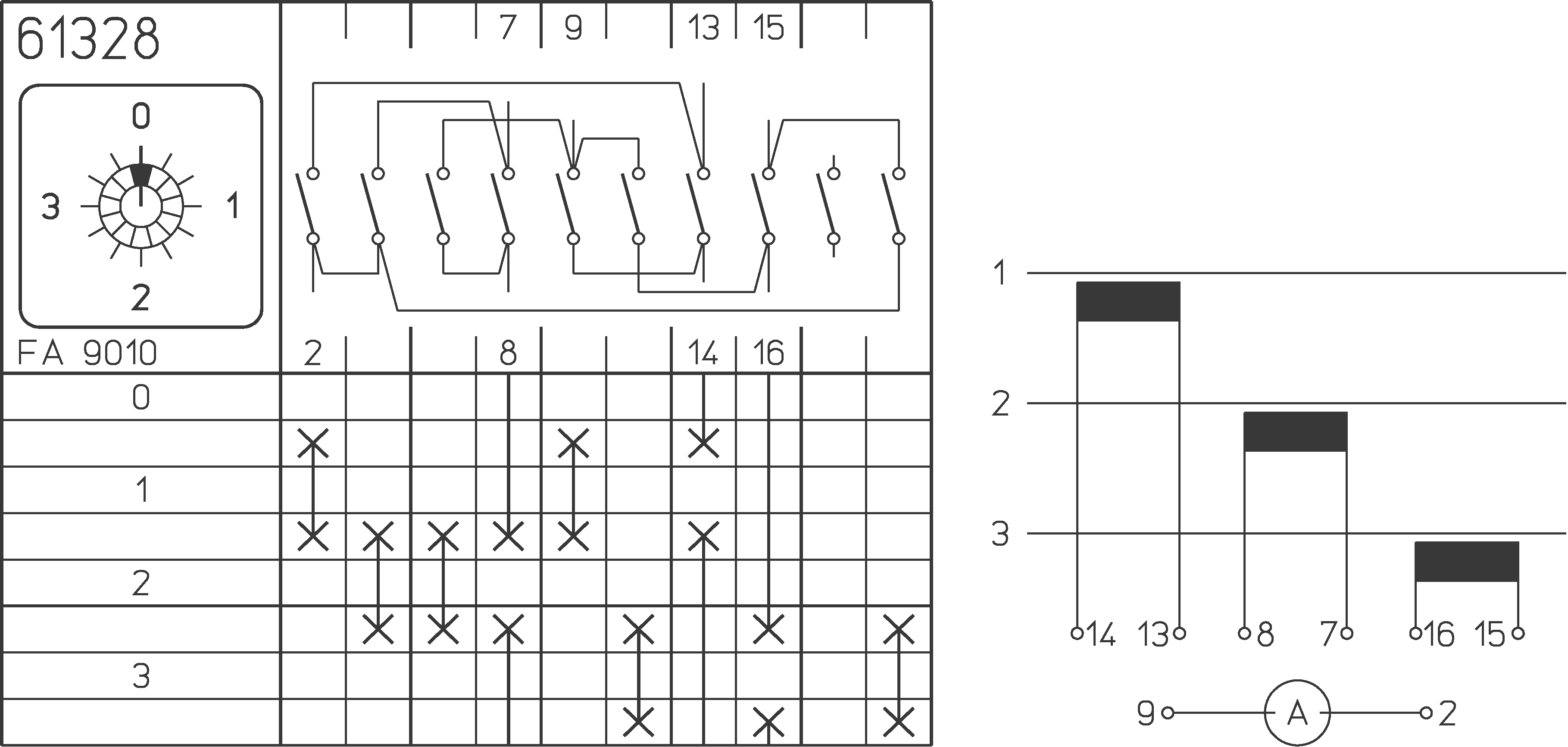
Technical information rotary cam switches switching programmes description stages contacts ident no. Rotary cam switches from salzer are manually operated independently programmable.

Boat Switch Wiring Diagram Diagram Base Website Wiring
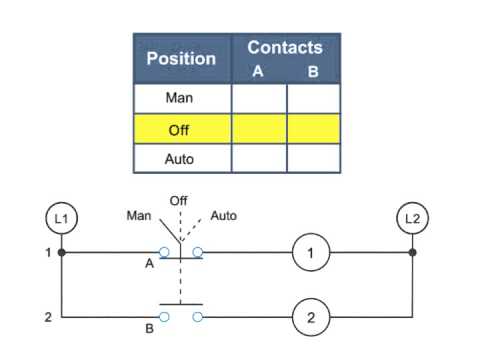
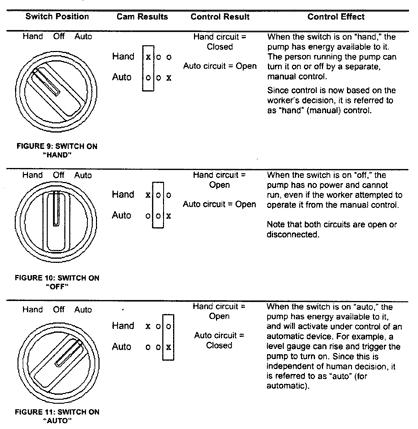
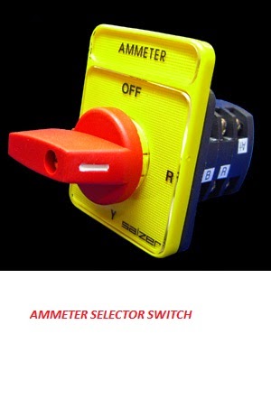
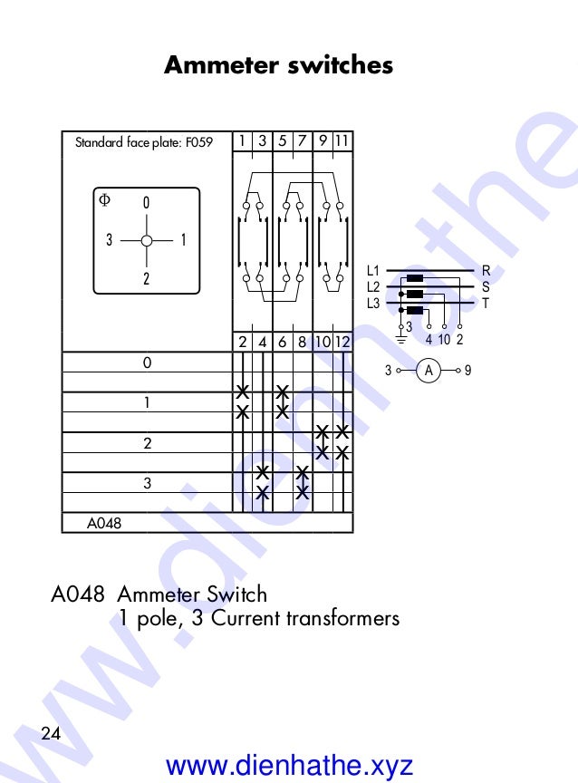
Salzer ammeter selector switch wiring diagram. Salzer ammeter selector switch wiring diagram. A complete guide of ammeter selector switch wiring diagram or rotary switch wiring diagram for 3 phase system load testing. Figure g water level switch schematic. Preparation of a diagram completing a wiring of dol starter with overload trip connection with ammeter with selector switch pt with. Whirlpool dryer wiring diagram. With inscription ammeter selector switches with off 1 transformer 1 pole 1 2 61321.
Switching diagrams and further switching programmes page detailed. 8n ford tractor wiring diagram. Ammeter selector switch with centre off 3 transformers 1 pole. Voltmeter selector switch wiring diagram for three phase. In this video i guide complete about ammeter rotary switch and its. Ammeter switches with 0 position start selector switches.
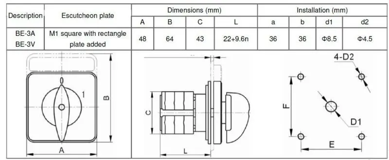
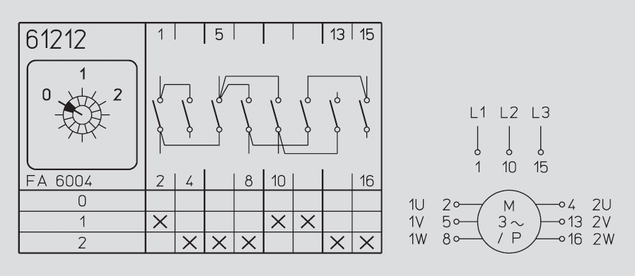
So come to the ammeter selector switch wiring diagram 3 days ago i am downloading and collecting some e book for him self and i find out a wiring connection diagram of amp selector switch in a e book pdf file which i highlight with text and make more easy to understand and you can see it below. Salzer selector switch 20a. 61321 61321a 61321b 61321c 61321g 2 transformers 1 pole 3 phase 3 transformers 1 pole 3 transformers 2 pole 2 3 5 4 6 9 61331. 20a 2 these switches have 2 to 8 positions and 1 to 12 stages 3 widely used to change position of ammeter and voltmeter to control the direction of mot.
Gallery of Salzer Ammeter Selector Switch Wiring Diagram