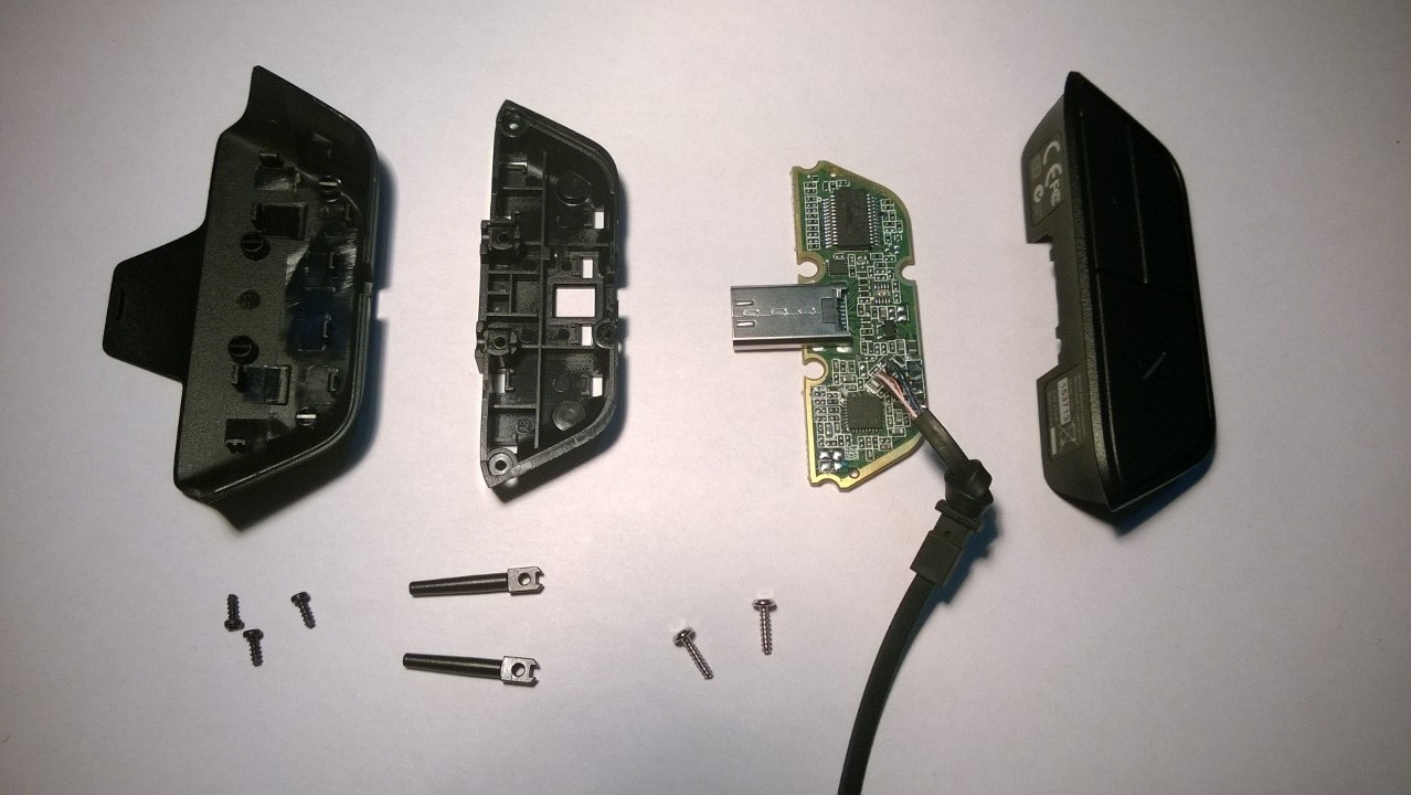
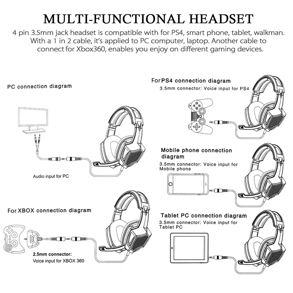
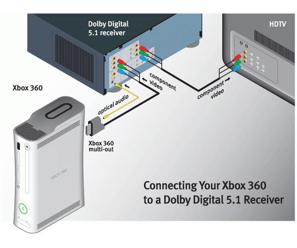
You will be attaching 4 wires to 3 terminals and 2 will need to be grounded together in order to function properly. Official xbox licensed headset.
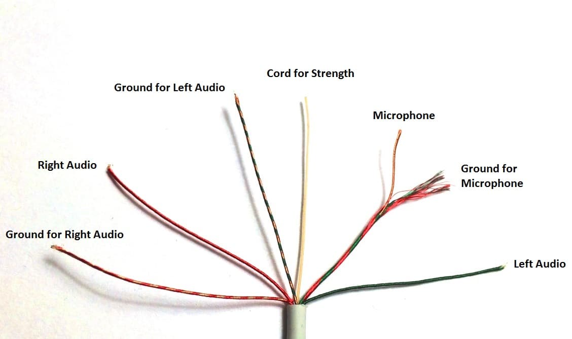
How To Hack A Headphone Jack
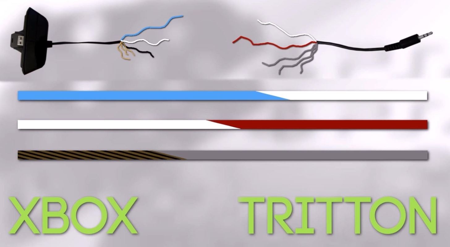
Xbox headset wiring diagram. The same process will work on 25mm jacks. The red and green wire which has the white wire inside it. The little white wire inside the red and green wire is the mic ground. The xbox kinect when you purchase it on its own will come with a usb converter cable therefore the usb diagram tells me nothing at allwiring diagram for kinect along with kinect wiring diagram along with xbox hdmi diagram moreover ps3 headset wiring diagram further exercise05 along with usb 1 0 cable wiring diagram moreover xbox parts. You can keep using the stock xbox one headset with the new adapter you made. All you need to do is attach a male 35mm plug to the end of the chat headset in order to keep using it.
Two separate insulated wires each with its own signal wire and a ground wire inside. Follow the diagram to put your headset together. Otherwise the arrangement will not function as it ought to be. Each component should be set and connected with other parts in particular way. The microphone will not work if the boom is inserted incorrectly. Clouds award winning comfort will keep you gaming strong during those marathon gaming sessions.
Separate insulated wires for the ground right audio and left audio inside a single cable. You must follow the ctia wiring diagram for the 35mm jack for xbox one. Cloudx was tested by microsoft and works with xbox one controllers that have a 35mm headset jack and elite wireless controllers. Usually red wires are the right audio channel and blue wires are the left audio channel. Mute mute to mute your headset slide the mute switch to reveal the red color. Twist this ground together with the copper ground posn 3 gnd.
The video explains the plugs shows how to test and. Xbox one headset wiring diagram xbox one headset wiring diagram every electric arrangement is composed of various different components. The red wire is right speaker and solders to ring 1. The green wire is left speaker and solders to tip. Is the mic wire posn 4m on the diagram below. This is tricky to solder.
Besure to twist the redcopper wire with the plain copper wire the one wrapped over the white wire these are your ground wires they get soldered to the ring 2. The red wire then is the left channel and blue is the right channel and are each connected to the ground copper wire upstream on the headset end at the speaker drivers. Hi this video shows you how to replace the 35mm 18inch jack on a gaming headset or headphones. Important when inserting the boom align the notches on the boom jack and port. White is the mic and its copper sleeve around it is the mic ground. Use the lighter to burn off the white insulation.

