T4 automatic pool cover owners manual save t 3 automatic pool cover owners manual mar 2012 or later step saver manual pool cover owners manual mar 2011 rel 0007 autosave spa cover owners manual mar 2010 or later. Detach the key switch box from the existing flex conduit and attach it at the new location.

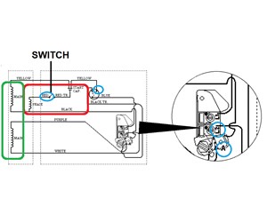
Diagram Based Inground Pool Wiring Diagram Schematic
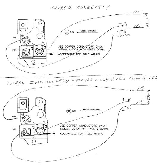
Pool cover switch wiring diagram. Assortment of automatic pool cover wiring diagram. Switch is to be remotely located the pool cover must be completely visible at all times. Then wire the motor and key switch as explained in the wiring diagram. Turn the key to feed the ropes onto the rope reels. Make sure the cover sides are aligned straight to feed directly into the track. Key switch 120v hot neutral ground neutral dir 1 dir 2 ground pool cover housing npt watertight connector 14 awg min.
Click on the image to enlarge and then save it to your computer by right clicking on the image. A wiring diagram normally offers information regarding the loved one position and arrangement of gadgets as well as terminals on the gadgets to assist in building or servicing the tool. A wiring diagram is a simplified conventional pictorial representation of an electrical circuit. Run an extra conduit from the equipment pad to the remote location. It reveals the components of the circuit as simplified forms and also the power and also signal connections in between the devices. Conduit to 120 vac 15 amp dedicated gfci.
Assortment of automatic pool cover wiring diagram. Wire extended 8 past conduit end. These are minimum recommendations only. Conduit with three different colored wires and one ground. Pull 4 x 14 gauge different colored wires red blue yellow black through the conduit. Automatic pool cover wiring diagram swimming pool timer wiring diagram for spa pump wiring diagram new sta rite pool pump wiring.
Continue to pull the cover over the pool and release the.


