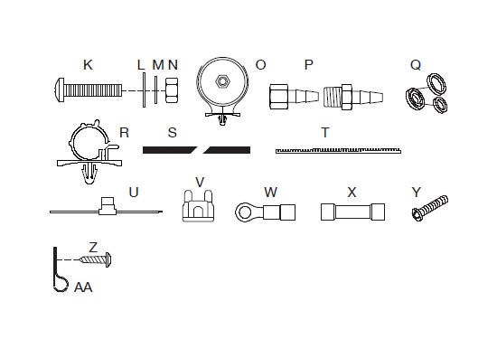
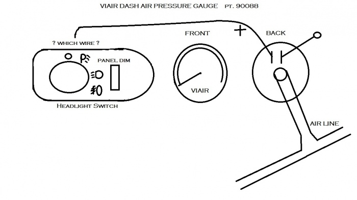
Pn 90110 85 psi on 105 psi off pn 90111 110 psi on 145 psi off pn 90113 90 psi on 120 psi off pn 90118 165 psi. Viair 90c compressor viair 90c compressor wiring diagram viair compressor pressure switch relay wiring diagram wiring the onoff switch.
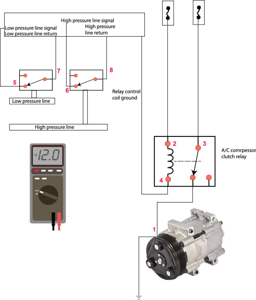
C604e8 Pressure Switch For Fan Control Wiring Diagram
Viair pressure switch wiring diagram. How to wire compressors for your air bag suspension duration. Attach one of the two remaining female terminal connectors to the wire that was routed from the pressure switch trigger wire small red wire on pressure switch with relay there are two male spade connectors on the back of the onoff switch. Single viair compressor wiring kit rev. Warranty info product registration become a dealer contact. Viair 90c compressor viair 90c compressor wiring diagram viair compressor pressure switch relay wiring diagram wiring the onoff switch. 12v when ignition is on supplied 40 amp fuse to constant 12v battery instructions 1.
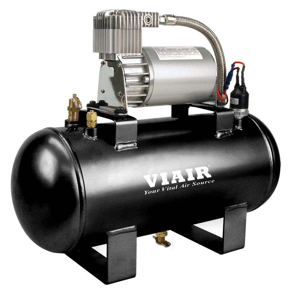
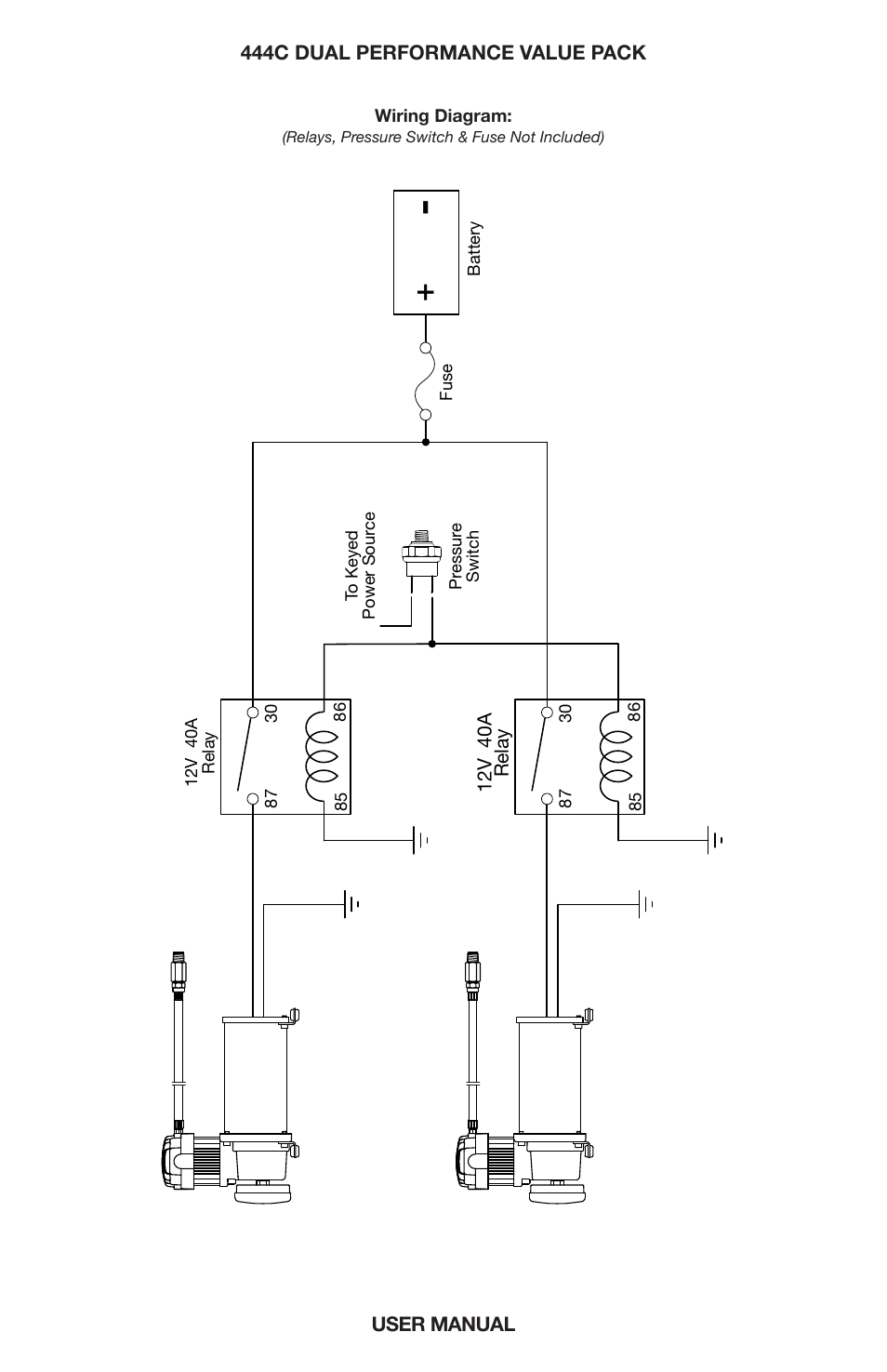
Wiring diagramsingle viair compressor wiring kit rev. Dual viair compressor wiring kit rev. 0111 30 87 85 86 40 amp relay pressure switch ground to compressor wire 12v accessory input. Home electrical pressure switches wrelay. Viair dual 444c on board air system. Wiring plumbing diagrams.
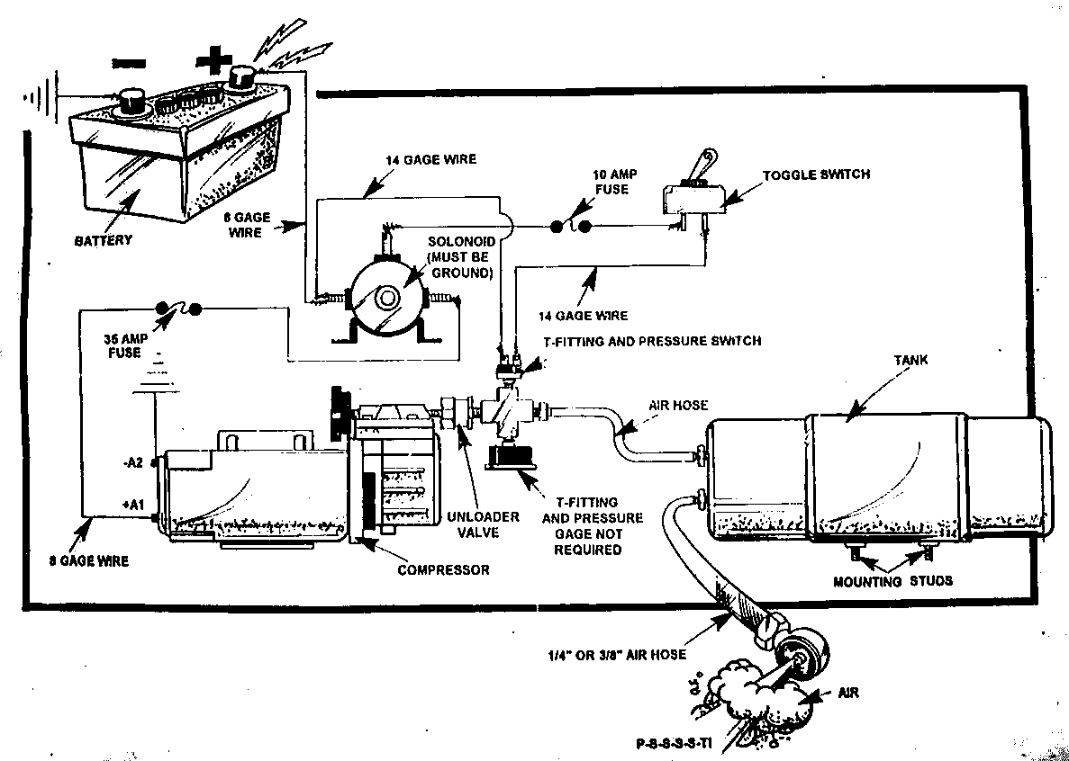
Plug in the compressor plug and you have power flowing to the air compressor through perhaps an onoff switch and to the pressure switch and if the pressure switch is closed power will flow through it to the start capacitor on the air compressor motor. Basic air suspension compressor wiring installation with relay and pressure switch. Viair recommends that you reference the chart below in order to determine the length and gauge of wire when installing your compressor. Compressor tank pressure switch gauge and system onoff switch. I have the viair constant duty on board air system. 0111 30 87 85 86 40 amp relay pressure switch ground to compressor wire 12v accessory input.
Disconnect terminal of the battery 2. American wire gauge awg for 12 volt circuits total. I wanted to bounce an idea off the group trying to make sure my logic is sound. 0407 30 87 85 86 30 87 85 86 pressure switch 40 amp relay ground to compressor wire 1 12v accessory input. 12v when ignition is on. Attach one of the two remaining female terminal connectors to the wire that was routed from the pressure switch trigger wire small red wire on pressure switch with relay there are two male spade connectors on the back of the onoff switch.
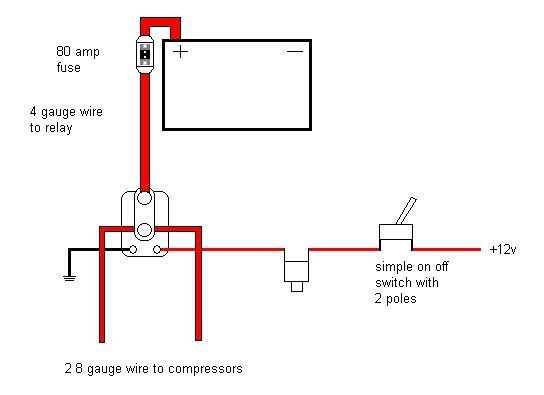
The typical wiring per the instructions is to run ignition switched power to the system onoff switch. Run power from the system onoff switch to the pressure switch and 12v fused power from the.

