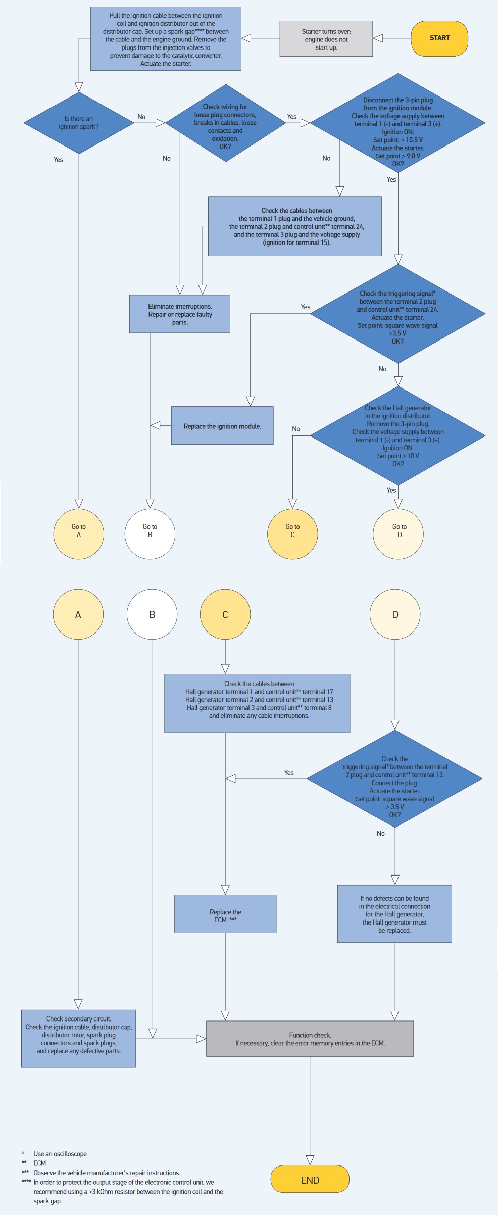
All of the information you need to diagnose a no start problem caused by the ignition module or the ignition coil or the distributor pickup coil. Step 1 locate ignition module.

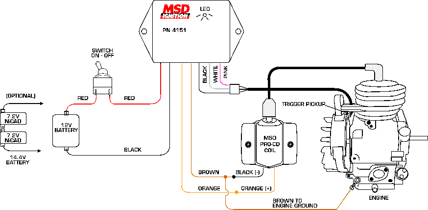
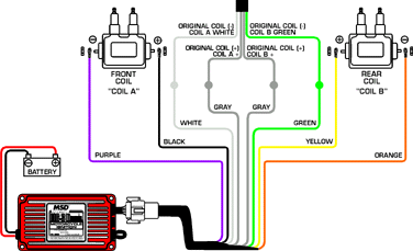
Basic Sensor Testing Amp Wiring Diagram
Tp100 ignition module wiring diagram. Locate the terminals running into and out of the ignition module. Ignition 12v ignition coil inj1 inj2 inj3 vw hall dissy inj4 idle stabilizer o blue ground coil ve brown tp100 ignition module short redyellow hall ve brown rev counter input hall v ignition 12v 0 5 green magnetic dissy toyota honda etc or fiat uno crank trigger magnetic ve thick red purple 1mm black water temp 5v supply greyred or. One wire is grounded to the body pin 2 from the right thats fine the other 3 i have no clue how to wire. Where possible the ignition module should be mounted on a metal surface and in an air flow region to aid cooling. Aftermarket tp100 ignition module of high quality built by dicktator with high qulaity electronic igfet components. You can find the ignition control module test explained here.
As you might guess the placement can change based on the type of vehicle so it is important to have the correct diagram or you will be practically going in blind. To locate the ignition module refer to a wiring diagram for your vehicles particular make and model. Use a wiring diagram for the year model of your vehicle. Ignition coils with a resistance up to 1 ohm and 6mh inductance will work however spark energy may suffer. Ford ignition system circuit diagram 1994 1995 49l 50l and 58l. These modules have no internal electronic rev limiter such as the vw tp100 modules and are compatible with any engine management system aftermarket or standardfor eg.
Testing of the ignition module can be done using a digital volt ohm meter and a 12 volt test light. You can find the 1994 1995 ignition system wiring diagram here. It has 7 pins and 4 wires. Diagnostic manual comes with. Ignition system no start problem diagnostic manual. Ignition module wiring diagram posted at may 20 2020 636 by admin in design beloved viewers when you are searching the new ignition module wiring diagram circuitry representation collection to read this day ignition module wiring diagram can be your referred wiring representation.
How to test the ford ignition control module. Alright guys while changing the gle fuel filter i mistakely pulled off the 3 wires coming from the distributor to the tp100 module or something. Placement of the module varies from model to model so check the appropiate service manual of your vehicle for the. Do not mount the module directly on the engine or on the firewall near the exhaust. Complete step by step testing instructions. In the next page youll find the icm connectors pinout with a brief description of each wire.


