Learn how this truth table illustrates the manual or automatic contact positions of two contact selector switch. For mfj 8621 31 vhf dataradio transceivers with 5 pin din data io connector.
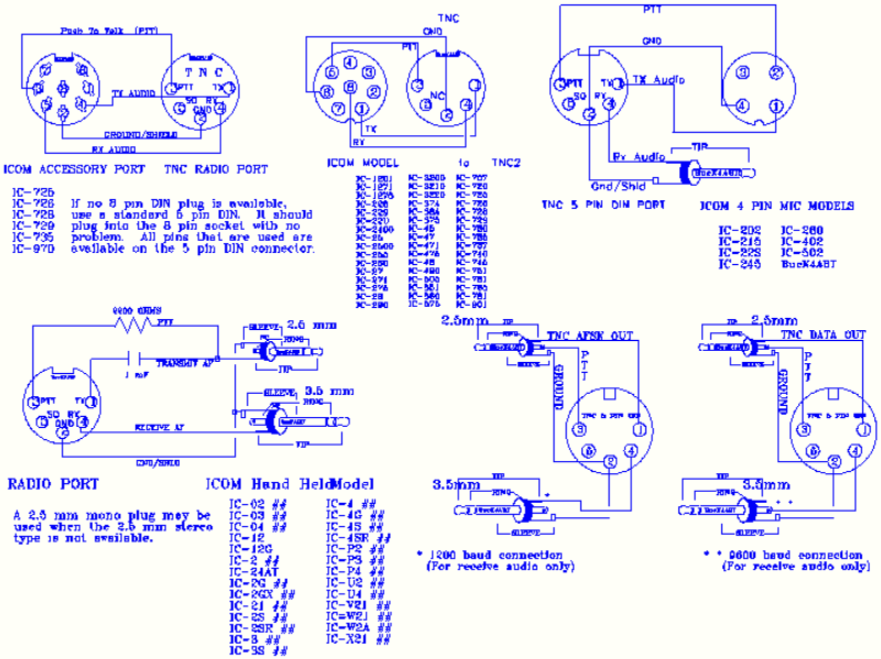
Connection Diagrams Tnc To The Transceiver I1wqrlinkradio Com
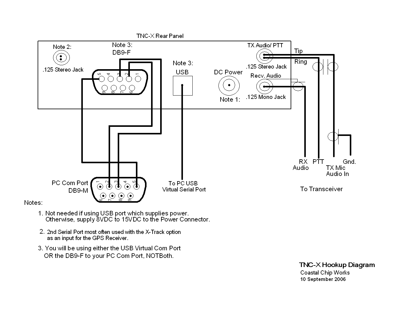
Tnc switch wiring diagram. Now the tnc switch should return to neutral positin due to spring action. This circuit is wired the same way as the 3 way lights at this link. Pcb 88 is an internal pc tnc card with dedb9 radio interface connector. For sections of the pen. Three wire cable runs between the switches and the outlet. Mfj dataonly transceivers to various tnc.
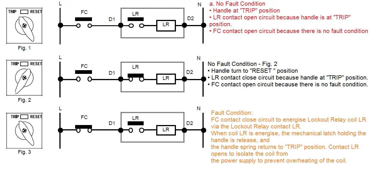
The source is at the sw1 where the hot is connected to. 10 mm ² copper aluminum 16 mm ² for sections of lower electrical conductors must change tns. Contact position on a selector switch can easily be illustrated using truth tables. Interface diagram for aea pcb 88 to mfj 8621 31 vhf dataradio transceivers with 5 pin din data io connector. 3 way switched outlet wiring. In the wiring diagram tnc 230v 400v show two drivers who leave pen.
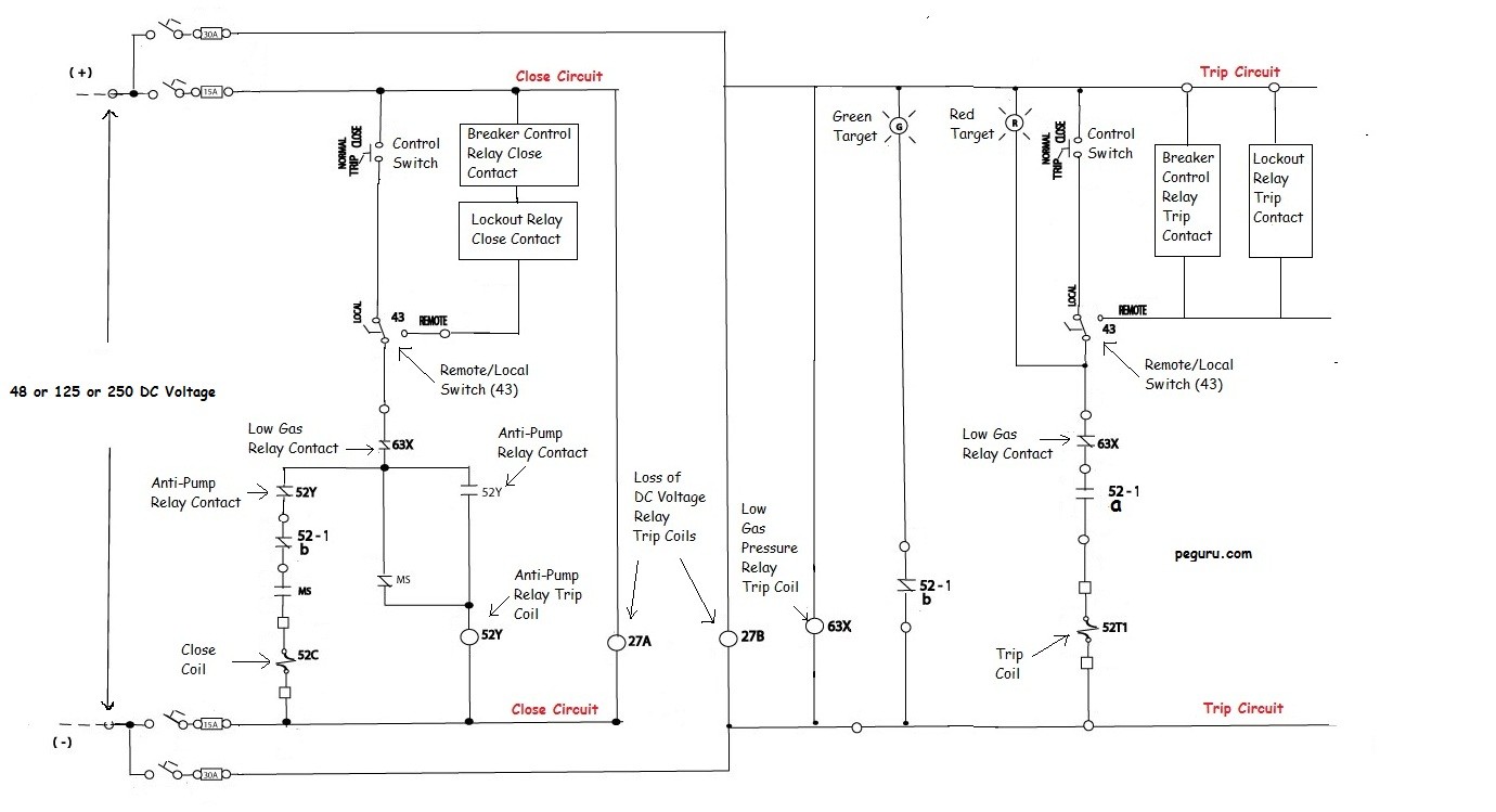
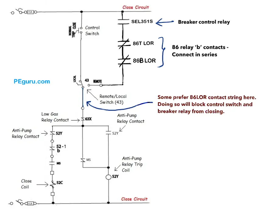
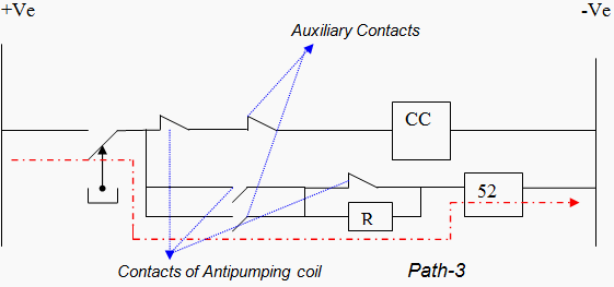
In this diagram two 3 way switches control a wall receptacle outlet that may be used to control a lamp from two entrances to a room. But let say at the same instant the tnc switch spring fails and due to which the tnc switch does not return to neutral position but gets stuck at the close position. It would be better to make a bridge over the mass of the receiver to show that the protective conductor has priority over the neutral conductor. Lets say tnc switch is turned to close postion the positive is extended to closing coil.


