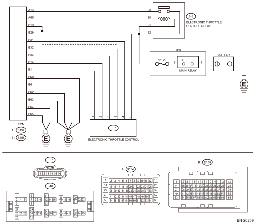
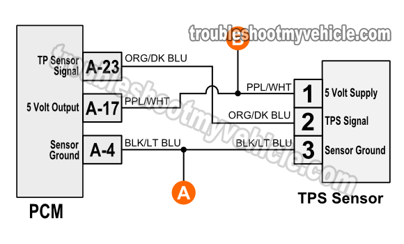
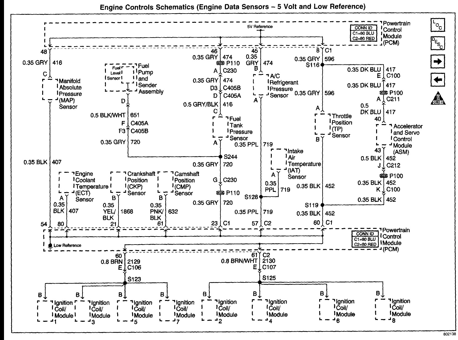
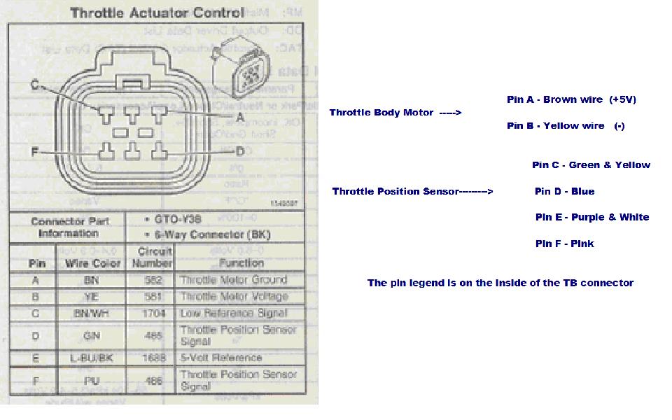
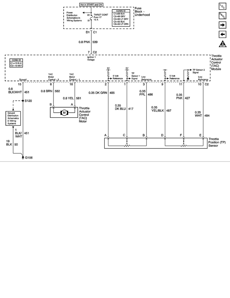
The throttle position tp sensor and accelerator pedal position app sensor are the only sensors sending data to the powertrain control module pcm that the vehicle operator has direct control over. Throttle position sensor tps wiring diagram.
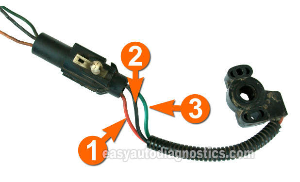
Part 1 Throttle Position Sensor Tps Test Ford 5 0l 5 8l
Throttle position sensor wiring diagram. Carries the throttle angle voltage signal that the tps creates to the pcm. A third wire is connected to the vcm to measure the voltage from the tps. Black is ground and should be tapped into the black main ground wire from vehicle pin 16 orange is the 5 volt reference. Throttle position sensor wiring diagram dodge throttle position sensor wiring diagram ford throttle position sensor wiring diagram gm throttle position sensor wiring diagram every electric structure is composed of. The throttle position sensor tps wiring diagrams and info in this page apply only to 1997 1998 16l honda civic. Heres a brief description of the throttle position sensor tps circuits.
The first component is symbol that indicate electric component in the circuit. The throttle position sensor tps wiring diagram and info in this page apply to 1997 1999 ford 46l 54l vehiclesmodel years. The pcm provides 5 volts dc on the yelblu wire to both the throttle position sensor fuel tank pressure sensor and the egr valve lift sensor on vtec e only. It is a potentiometer with one end connected to 5 volts from the vcm and the other to ground. Ford throttle position sensor connections ford has two different color codes for throttle position sensors and several different connectors and pin outs. The tp sensor is a three wire potentiometer that provides an analog signal to the computer.
There are just two things that will be found in almost any throttle position sensor wiring diagram. A circuit is usually composed by many components. The throttle position sensor tps is connected to the throttle shaft on the throttle body. The early style color code mostly matches the wiring of our harnesses. Another thing you will see a circuit diagram could be lines. Wire that feeds the tps with 5 volts dc from pin 90 of the pcm.


