Voltmeter 3 phase 3 wire 236 372 ammeter 1 pole 3ct360off 323 640 1. Lw28 20 20 660 440 20 20 1575157511 553515 4 240 5 1 120 5 lw28 25 25 440 25 25 22 11 22 11 15 7565 3 5 240 8 15 120 9 lw28 32 32 440 32 32 30 15 30 15 22 11 1155 6 240 14 11 120 25 lw28 63 63 440 63 63 57 30 57 30 361851575 120 55 lw28 125 125 125 125 125 1004510045 50 22 18 12 90 lw28 160 160 160 160 160 1155711557 65 33 25 15 110.

Lw28 20 2 C04 Universal Changeover Switch Combination Switch
Lw28 20a wiring diagram. Our switch can be custom 20a4 poles you can send me wiring diagram. Cam switch lw28 20 lw26 20 control motor changeover switch 20a 4 stages 4 poles custom switches high voltage ymw26 204 attention. Eaton wiring manual 0611 4 4 4 4 circuit diagram example for maintenance switches with a load shedding contact and or switch position indicator t03 3 15683 maintenance switch t03 3 15683 circuit symbol function load shedding. Image 3 has shown which terminal will be connected in different position please read the wiring diagram as a reference. Lw28 202 3 positions1 0 2 2 phases 8 terminals latching type switch ui 550v ith 20a. When switching on the main current contacts close first then the contactor is activated via the late make no.
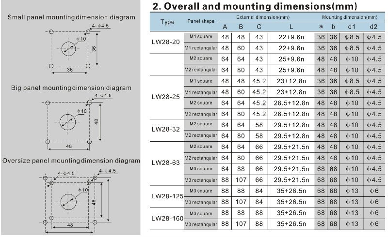
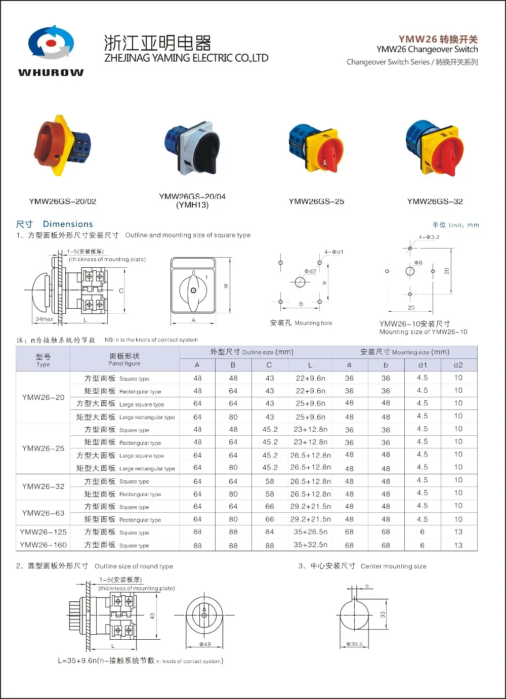
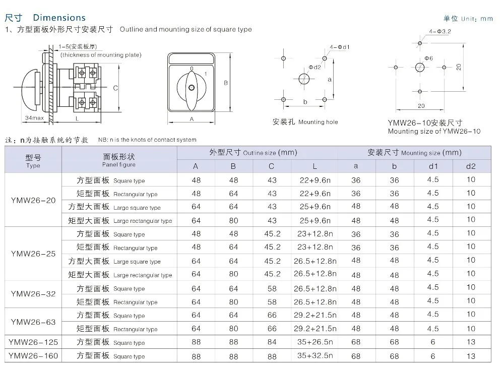
Lw28 series is mainly used for communications switch 50hz rated voltage 440v and below dc voltage 240v below and rated current to the electrical wiring 63a for manual less frequent switching circuit breaker or controlling and conversion may also directly control three phase induction motor and made to measure and control circuit. 20a rotary cam switches 6 max 43 20 l 39 round bezel 49 square escutcheon plate 223 241 32 48 33 305 mounting holes contact configuration rs stock no stages connection diagram onoff switches with switching 1 pole 2 pole 4 pole 3 pole 6 pole 8 pole 323 561 323 577.


