Lection and wiring instructions. Charles illinois 60174 1 800 sensor2 fax.

2151t Products System Sensor System Sensor
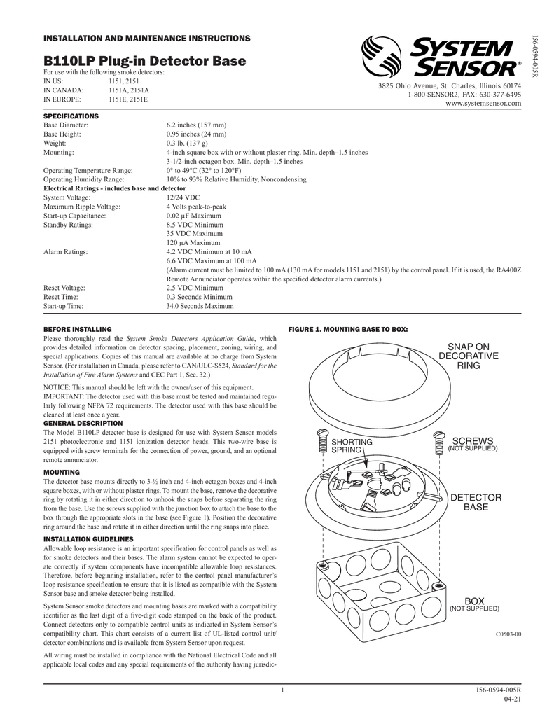
System sensor 2151 wiring diagram. B114lp typical wiring diagrams b114lp base terminals no. This manual should be left with the owneruser of this equipment. Copies of this manual are available from system sensor. Charles illinois 60174 1 800 sensor2 fax. All bases are provided with screw terminals for power ground remote an. 21512151t low profile photoelectronic plug in smoke detectors installation and maintenance instructions 3825 ohio avenue st.
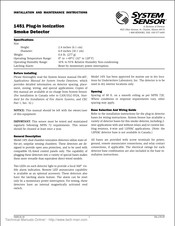
The system sensor 2151 low profile photoelectric smoke detector with a b114lp or b114lpbt base is listed to. Function 1 remote annunciator 2 not used 3 not used 4 remote annunciator 5 not used 6 no. Before installing this smoke detector including 2 wire applications with and please thoroughly read the system sensor manual a05 without relays andor current limiting resistors 4 wire and 1003 applications guide for system smoke detectors 120vac applications. Test the detector using the magnet as described under a. Please thoroughly read the system sensor manual a05 1003 applications guide for system smoke detectors which provides detailed information on detector spacing placement zoning wiring and special applications. System sensor has a variety of detector bases available for this smoke detector including 2 wire applications with and with out relays andor current limiting resistors 4 wire and 120vac applications.
2151 low profile photoelectronic plug in smoke detector installation and maintenance instructions 3825 ohio avenue st.


