13 check voltage supplied to the heater refer to the heater data plate for voltage requirements. Connect one supply wire to the upper black wire.
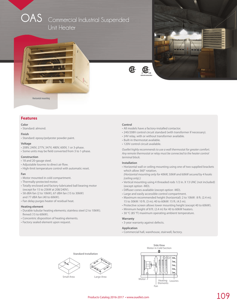
Oas Commercial Industrial Suspended Unit Heater Manualzz
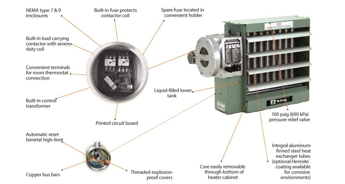
Ruffneck heater wiring diagram. The ruffneck line has enhanced thermon heating systems. Ruffneck troubleshooting tips 1. Refer to applicable electrical codes for additional information. Multi watt baseboard heater right or left wiring 120v or 240v supply. Heater is not operating 11 check all fuses in heater control box. Ruffneck features a wide selection of explosion proof heaters heating systems and heating accessories such as unit heaters forced air heaters electric heaters heat exchangers wash down unit heaters and more.
Wiring diagrams for actual wiring circuit of unit reference circuit type listed on rating plate. Ruffneck from thermon heating systems is renowned for its rugged reliable and versatile heavy duty explosion proof heaters heating systems and heating accessories. Connect one supply wire to one heater wire. Replace wiring compartment cover and secure with screw previously removed. Heater is to be used only in atmospheres having an ignition temperature higher than the heaters maximum rated operating temperature as shown on the heater data plate. Wiring diagrams residential electric water heaters current production 315267 000 time clock switch operates bottom element only to power supply to time clock switch off peak meter operates to power supply to off peak clock 2 wire 1 phase.
Heater to be used only in the hazardous locations indicated on the heaters data plate. Thermostat wiring diagrams for heat pumps heat pump thermostat wire diagrams. Ruffneck has a long and proud history of supplying quality heating products for the harshest industrial environments to a worldwide customer base for over 30 years. Turn power back on at the electrical panel board. 14 check thermostat by turning it and check continuity with a multimeter. Cci thermal technologies ruffneck product line offers the industry standard in heavy duty heaters for harsh industrial environments such as outdoor extreme weather environments.
3ø wiring diagrams 1ø wiring diagrams diagram er9 m 3 1 5 9 3 7 11 low speed high speed u1 v1 w1 w2 u2 v2 tk tk thermal overloads two speed stardelta motor switch m 3 0 10v 20v 415v ac 4 20ma outp uts diagram ic2 m 1 240v ac 0 10v outp ut diagram ic3 m 1 0 10v 4 20ma 240v ac outp uts these diagrams are current at the time of publication. Connect remaining supply wire to remaining heater wire. 12 check remote disconnect switch and circuit breaker. Heat pumps are different than air conditioners because a heat pump uses the process of refrigeration to heat and coolwhile an air conditioner uses the process of refrigeration to only cool the central air conditioner will usually be paired with a gas furnace an electric furnace or some other method of heating.


