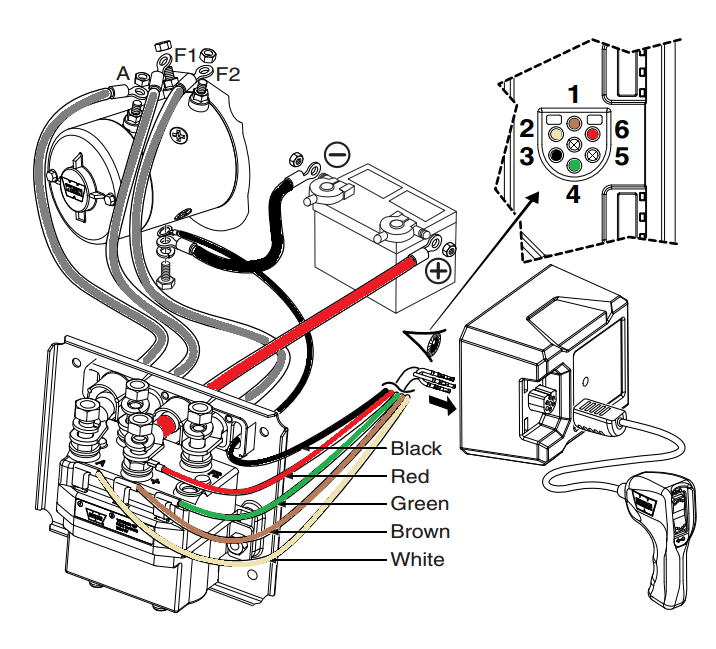
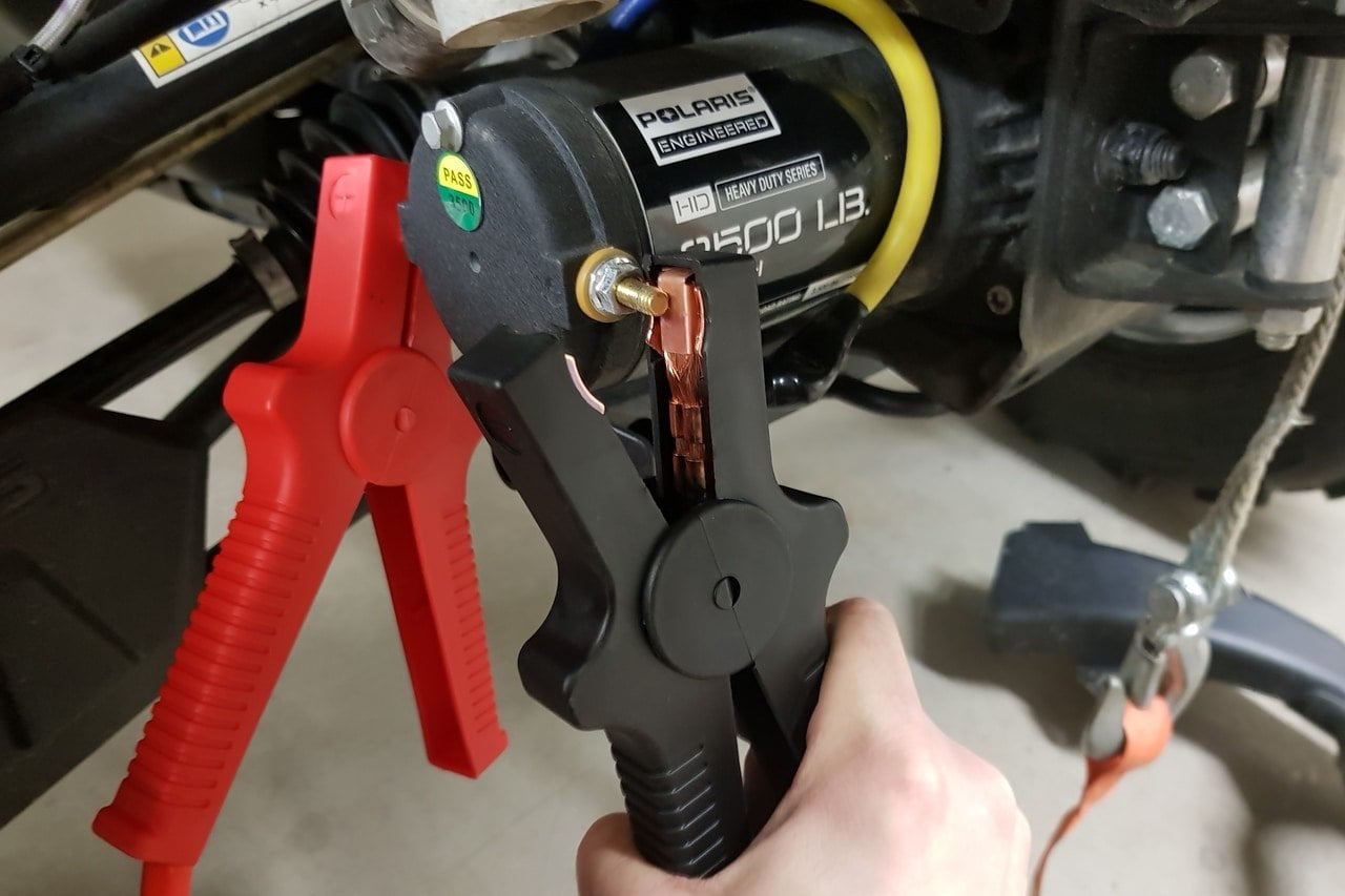
Z bracket assemble the bush and spindle onto the z bracket fit the flat washer screw on the nyloc nut and tighten. Connect the black negative cable to the winch black negative terminal.
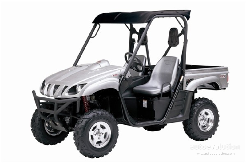
Lb Warn Winch Wiring Diagram 2000 Winch Toggle Switch Yamaha
Rhino winch wiring diagram. Always spool the winch rope onto the drum in the direction specified in the. Winch wireless remote control wiring diagram image. Yamaha fuel injector wiring diagram e26. Elite winch wiring diagram. To prevent serious injury due to accidental activation complete the winch installation before wiring. Winch wireless remote control wiring diagram image.
Max 2000 3000 clocking instructions. Winch wireless remote control wiring diagram collections of amazing winch controller wiring diagram 83 bulldog security wiring. To prevent serious injury due to accidental activation complete the winch installation before wiring. 3000 4500 rhino winch co rhino winch co 3 quick start guide mounting caution. Always choose a mounting location that is sufficiently strong to withstand the winch pulling capacity. With all the included features great price and added looks its hard to go past a rhino winch tough heavy duty materials 9500 lbs dyneema rope wired and integrated wireless remote control free battery isolator switch with key power cables pre insulated to save you time and money during install.
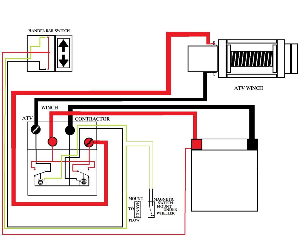
Elite and max differences. Elite and max 3500 5000 clocking instructions. Always choose a mounting location that is sufficiently strong to withstand the winch pulling capacity. The winchs solenoid is its power switch and main safety device. Rhino winch co rhino winch co 3 13500 175000 20000 quick start guide mounting caution. Wiring diagram for warn winch valid warn 2500 atv winch wiring.
Max winch wiring diagram. 2009 yamaha rhino 700 wiring diagram df995d6 wiring diagram for rhino 700 wiring diagram for rhino 700 2009 wy 6322 yamaha rhino fuse diagram. Always spool the winch rope onto the drum in the direction specified in the. Connect the red positive cable to the winch red positive terminal. When electricity is sent to the solenoid upon activation of the power switch a magnetic field causes the circuit to the winch to be completed and power to be sent to the device for operation. Rhino winch co rhino winch co 5 english wiring diagram 4500lb b b blue cable to motor yellow cable to motor red positive cable to battery black negative cable to battery connection to handlebar controller 1.
Fitting the winch and power roller to the longitudinal bars winch assemble the m10 x 20mm bolts channel nut and washers onto the winch and z bracket as per the diagrams ensure that the channel nuts are loose.


