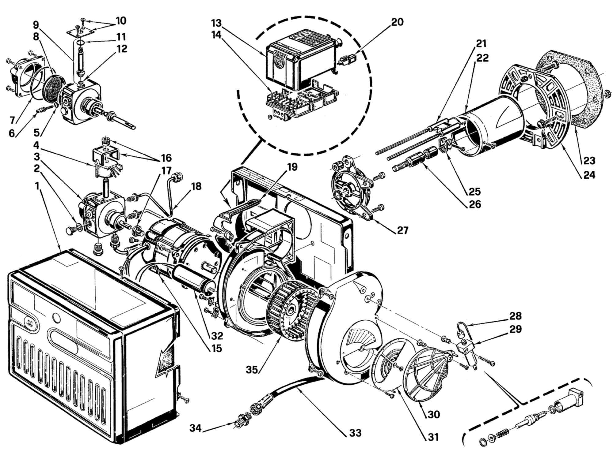
Package contents list package contents list your riello 40 burner should include the following parts. Installation use and maintenance instructions 20063817 1 032013 forced draught gas burner two stage operation code model type 3757714 riello 40 gs20d 577t1.
Product Page
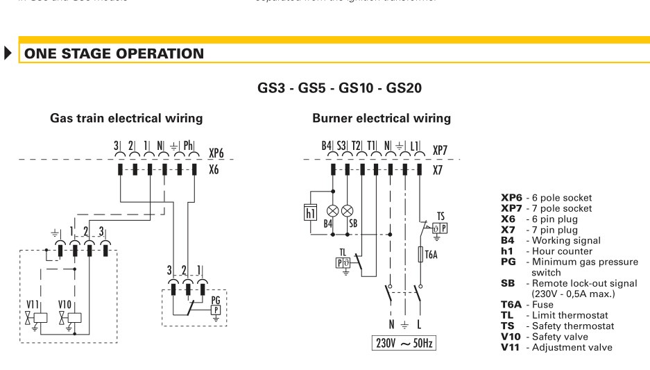
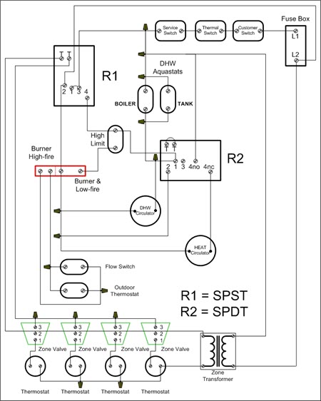
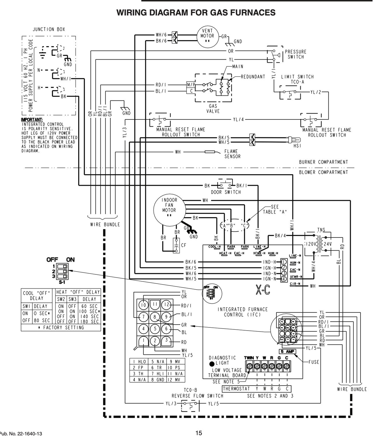
Riello burner wiring diagram. All wiring must be done in. The burner may be controlled using either a direct line voltage control circuit 120v ac 60 cycle or a low voltage control 24v ac 60 cycle using models riello or honeywell r8038a 24v relays. Application field wiring wiring diagram shown below for standard riello 530 sec primary control installation note. Riello warranty is subject to correct burner appliance and appli cation matching and set up in line with riellos instructions and guidelines. The settings in this manual are for retrofit applications. No warranty is given in relation to the use of components.
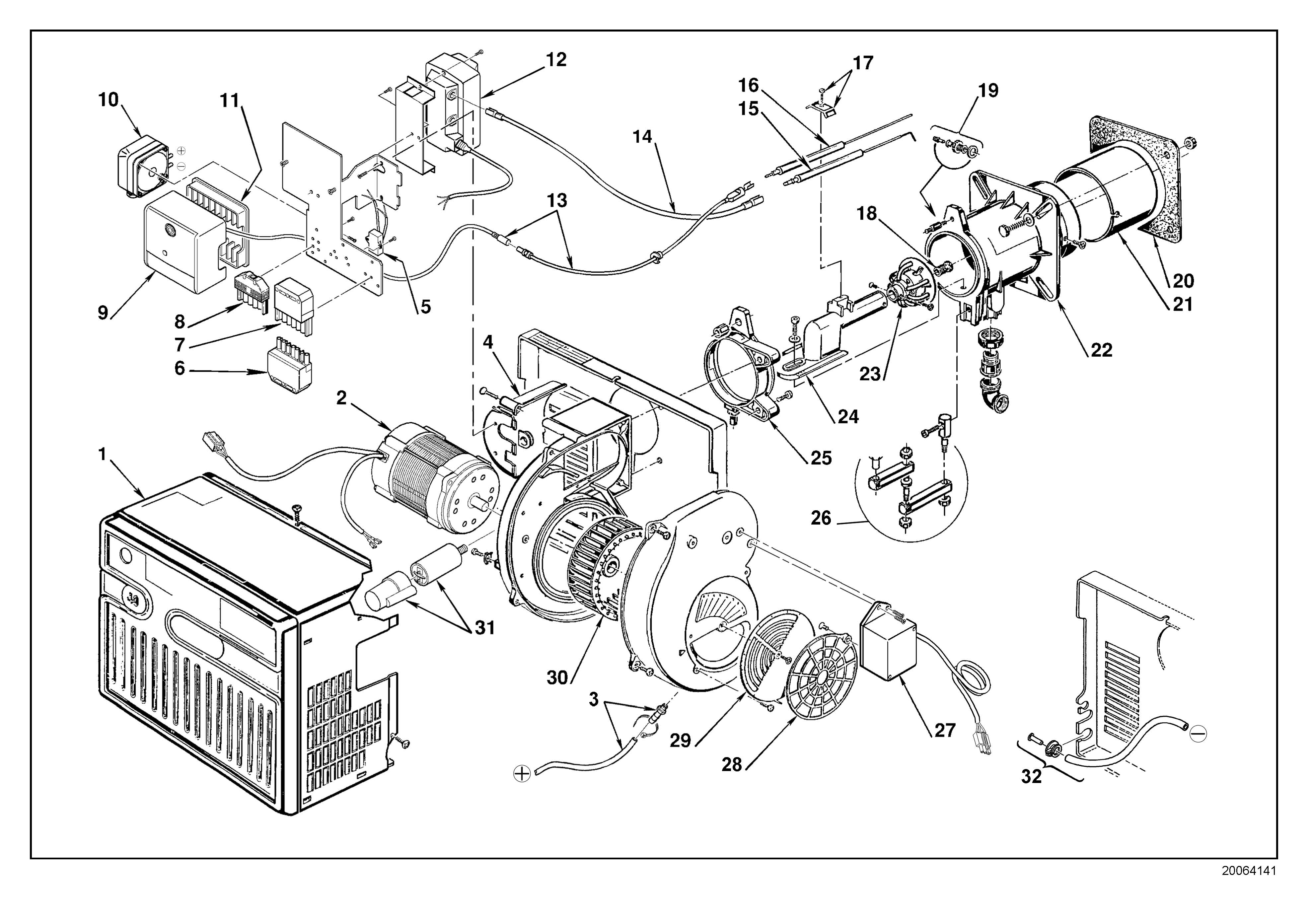
Riello parts lists diagrams parts list datasheets and diagrams for riello oil burners 24 hour delivery on genuine manufacturer boiler spares 30 day money back guarantee. Electronic air shutter requires a constant 120v power supply to the aux terminal failure to provide this will result 1n no burner operation or air shutter will not close. With a consolidated experience in over 90 years of great successes and innovations thanks to projects and solutions aimed to exploit efficiently all types of energy riello is the italian brand leader in manufacturing systems and technologies for heating and cooling in the residential and professional sector. Riello 40 series residential oil burners note. Riello will not be responsible for the improper attention installation or set up of the appliance. 3 t 4 operating limit device.
Electronic air shutter requires a constant 120v power supply to the aux terminal failure to provide this will result in no burner operation or air shutter will not close. Worldwide leader in burners production. If this burner is being installed on a packaged unit burner comes with the boiler or furnace then follow the settings on the oem page as settings may differburner is set for a single line system. Application field wiring wiring diagram shown below for standard riello 530 sec primary control box installation note. Table of contents application field wiring riello 530 sec 24 v. All components within th e hydraulic circuit suitable for bio fuel use and supplied by riello will be identified as bio com patible.
Diagram 14 firing ranges of riello rls series dual fuel burners 34 diagram 15 test combustion chamber for burners 34 diagram 16 firing range of riello rls100 two stage gaslight oil burner 35 diagram 17 firing range for riello ti series burner combustion heads 35 diagram 18 gas supply low pressure circuit 36 diagram 19 gas supply. Following the wiring diagram on the next page make electrical connections to burner. C6501010 standard f3 5 manual rev.

