120v 24v 24 vdc resistive. Collection of rib2401d wiring diagram.

Tt 6981 Rib 2401d Dpdt Relay Wiring Diagram Free Diagram
Rib2401d wiring diagram. The cover of the ribt series is removable and with star bushings or 12 conduit the coil drive wires can enter the housing through one of two convenient openings. A wiring diagram is a streamlined standard pictorial representation of an electric circuit. Relay contact wires exit the housing through a 12 or 34 npt nipple. Functional devices is the established leader in the hvac building controls and energy management industries for american designed and manufactured building automation and control devices. Rib2401b wiring diagram what is a wiring diagram. It reveals the components of the circuit as streamlined shapes and also the power and also signal connections in between the devices.
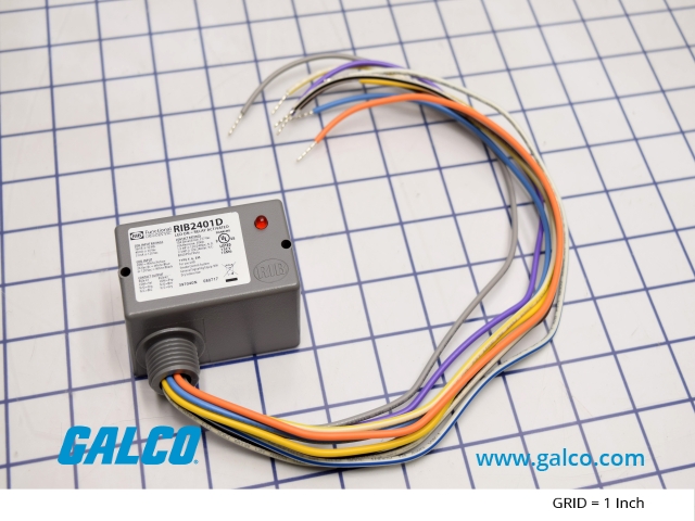
Adjoining wire routes might be revealed around where certain receptacles or components need to be on a common circuit. Tomorrow jul 10. 10 a horse power. Whtblk whtblu 24 vaddc whtyel comm nic comm org nic prp comm brn. Rib2401d wiring diagram architectural wiring diagrams reveal the approximate locations as well as interconnections of receptacles illumination and long term electric services in a building. Rib2401d wiring diagram what is a wiring diagram.
Functional devices 4 2195 each add to cart. Dpdt pilot duty rating. It shows how the electrical wires are interconnected and can also show where fixtures and components could possibly be coupled to the system. Rib2401d enclosed relay 10 amp dpdt with 24 vacdc 120 vac coil 20 ma at 20 vdc 24 ma at 24 vdc 36 ma at 30 vdc whtblk 120 vac whtblu 24 vacdc whtyel comm blu nc yel c org no gry nc prp c brn no specifications rib2401d rd red housing rib2401d n4 nema 4x housing ul508 only 10 amp pilot control relay. A wiring diagram is a simple visual representation with the physical connections and physical layout of your electrical system or circuit. A wiring diagram is an easy visual representation in the physical connections and physical layout of your electrical system or circuit.
It shows what sort of electrical wires are interconnected which enable it to also show where fixtures and components may be connected to the system. The coil drive wires are secured to screw terminals within a separate wiring compartment in the ribt.


