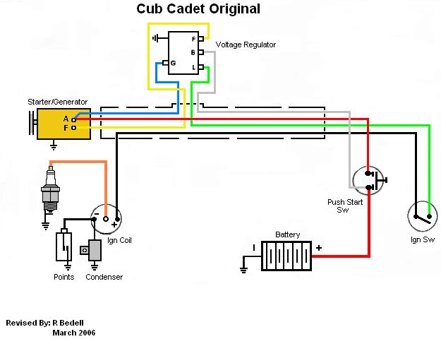
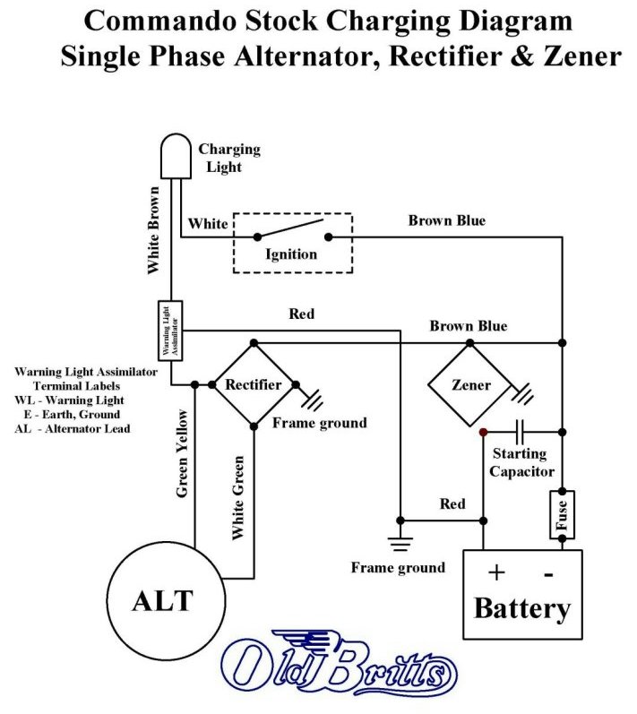
Each component ought to be set and linked to different parts in particular manner. Ripple factor in a bridge rectifier is half than that of a half wave rectifier.
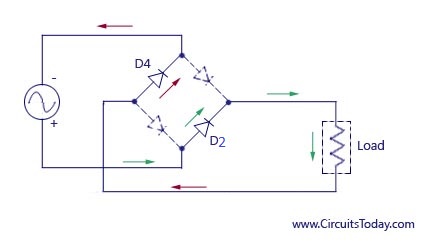
Full Wave Rectifier Bridge Rectifier Circuit Diagram With
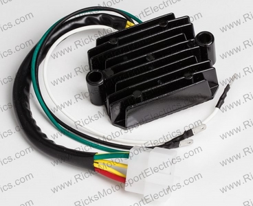
Rectifier wiring diagram. If not the structure will not work as it should be. Many ricks motorsport electrics rectifierregulators eliminate what is commonly referred to as a signal wire on oe pieces. The ac input is located between the diode pairs. Ripple factor in a bridge rectifier. Wiring a bridge rectifier is not a difficult project but you should print out the circuit diagram and diode symbols from the resource links and familiarize yourself with these symbols and the bridge rectifier diagram before you begin work. Ripple factor is a ratio of the residual ac component to dc component in the output voltage.
Full wave rectifier with capacitor filter. The bridge rectifier circuit is also known as two pulse bridge rectifier circuit b2. Mercury outboard rectifier wiring diagram mercury outboard rectifier wiring diagram every electric structure is made up of various unique pieces. The arrangement of the semiconductor diodes in the circuit of ac current flows in two different paths through the circuit. We will breake out the wiring into self contained groups ignoring all components except what is included in that group. This article will hopefully simplify the wiring on norton commandos.
Trail tech stators have yellow lighting leads. Connect to lighting leads from stator. For example on a 1981 kawasaki kz440 there are 5 wires going to the oe part. The circuit diagram below shows a half wave rectifier with capacitor filter. Trail tech regulatorrectifier 7003 rr150 2 yellow wires. Regulatorrectifier 7003 rr150 tech support.
Regulator rectifier terminal 1 grounded internally to key switch case alternator anti afterfire solenoid key switch ac output wire dc output wire ammeter headlights headlight switch battery terminal solenoid tab terminal s ta re terminal solenoid starter where is my small engine. Wiring diagram 5 pole switch briggs stratton part no. It consists of two parallel pairs of diodes. 2 yellow wires ac inputs whitered dc output blackyellow dc output and a brown wire.


