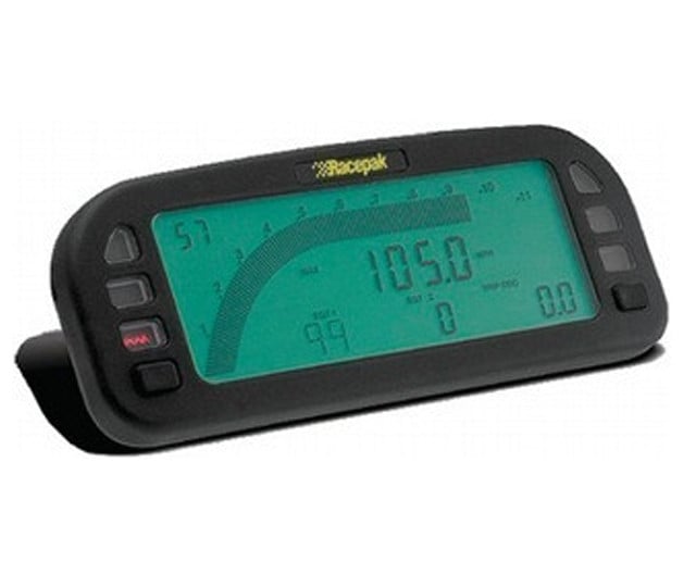
Variety of racepak iq3 wiring diagram. The udx display dash is designed to be used as an add on instrument for v series recorders.

Racepak Udx Warning Amp Shift Light Connectors
Racepak udx wiring diagram. A wiring diagram is a simplified standard photographic representation of an electric circuit. The dash has 4 programmable display pages. The ultra dash display allows for a single cable connection to the v net port on any racepak v series data logger. Udx dashes are capable of displaying up to 21 different functions. Racepak udx and iq3 overview for those looking at a used race car with racepak dash logger. It reveals the parts of the circuit as streamlined shapes as well as the power and also signal links in between the devices.
Udx digital display dash4 screens 20 programmable displaysplug n play installationwarning lights function buttonscommand center for a shift lightminimum maximum read outsadjustable lighting for night time usedisplay only dash is only used to display data that is being monitored by one of our v series data recordersdisplay only dash is designed to be used as an add on instrument for v. Racepak llc was founded in 1985 by spencer eisenbarth and ron armstrong originally as racepak and its parent company competition systems incorporated csi. There are 6 user programmable warning channels that can illuminate the internal warning leds and an. Both men were engineers with strong backgrounds in electrical and mechanical applications and both had an interest in motor sports. How to properly install wiring for a 24v minn kota trolling motor with a circuit breaker. The user can customize each page to display any channel they are currently data logging.
It will display any function that is being monitored by the recorder to which it is attached.


