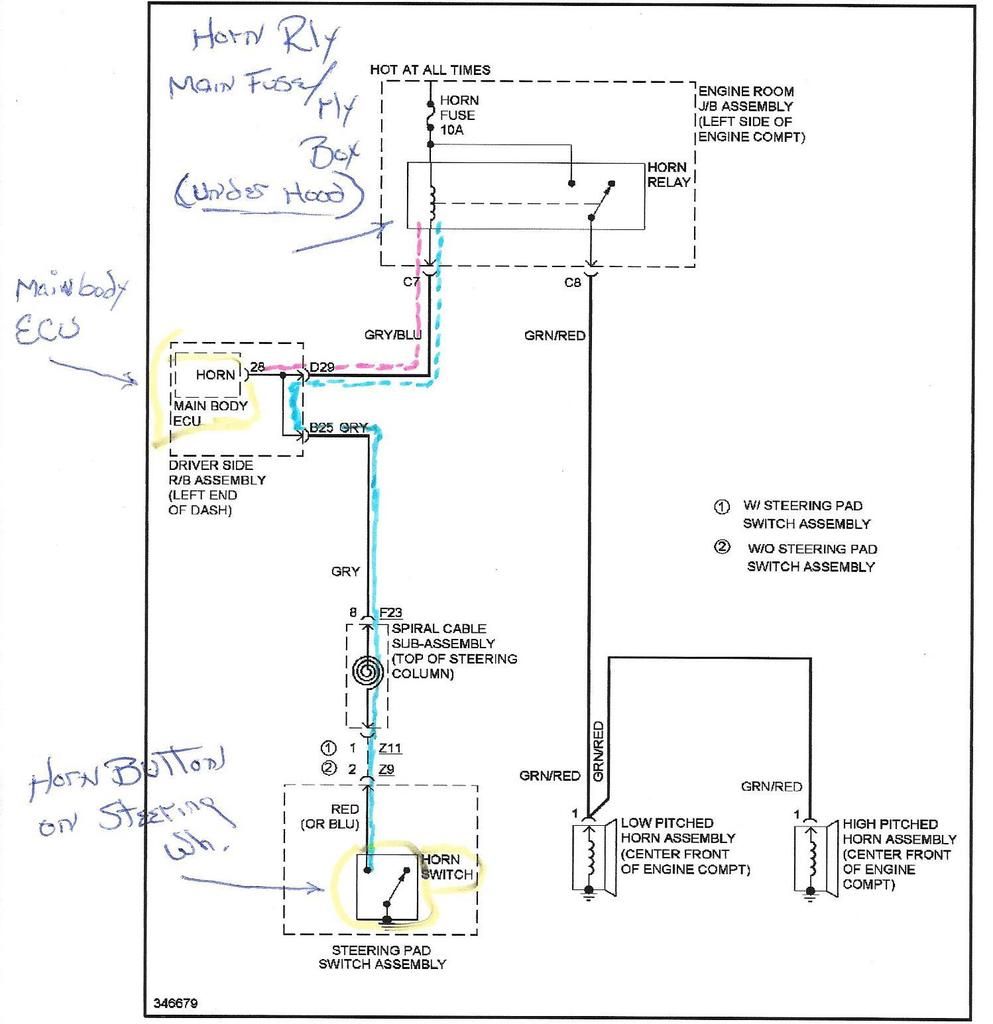
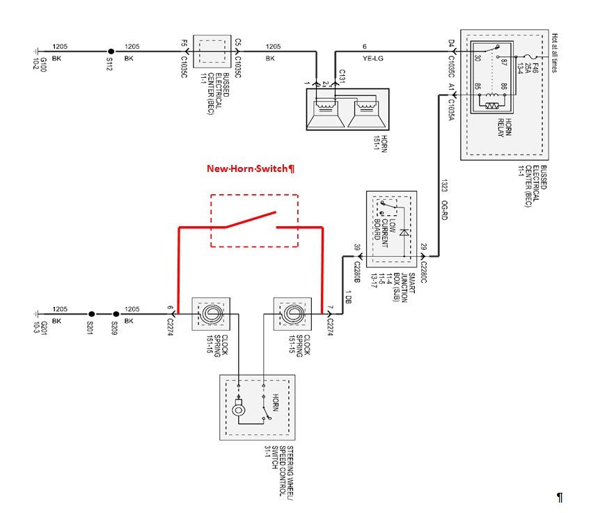
Almost all button are available momentary and latching. A simple system as the vehicle horn is not that simple any more.

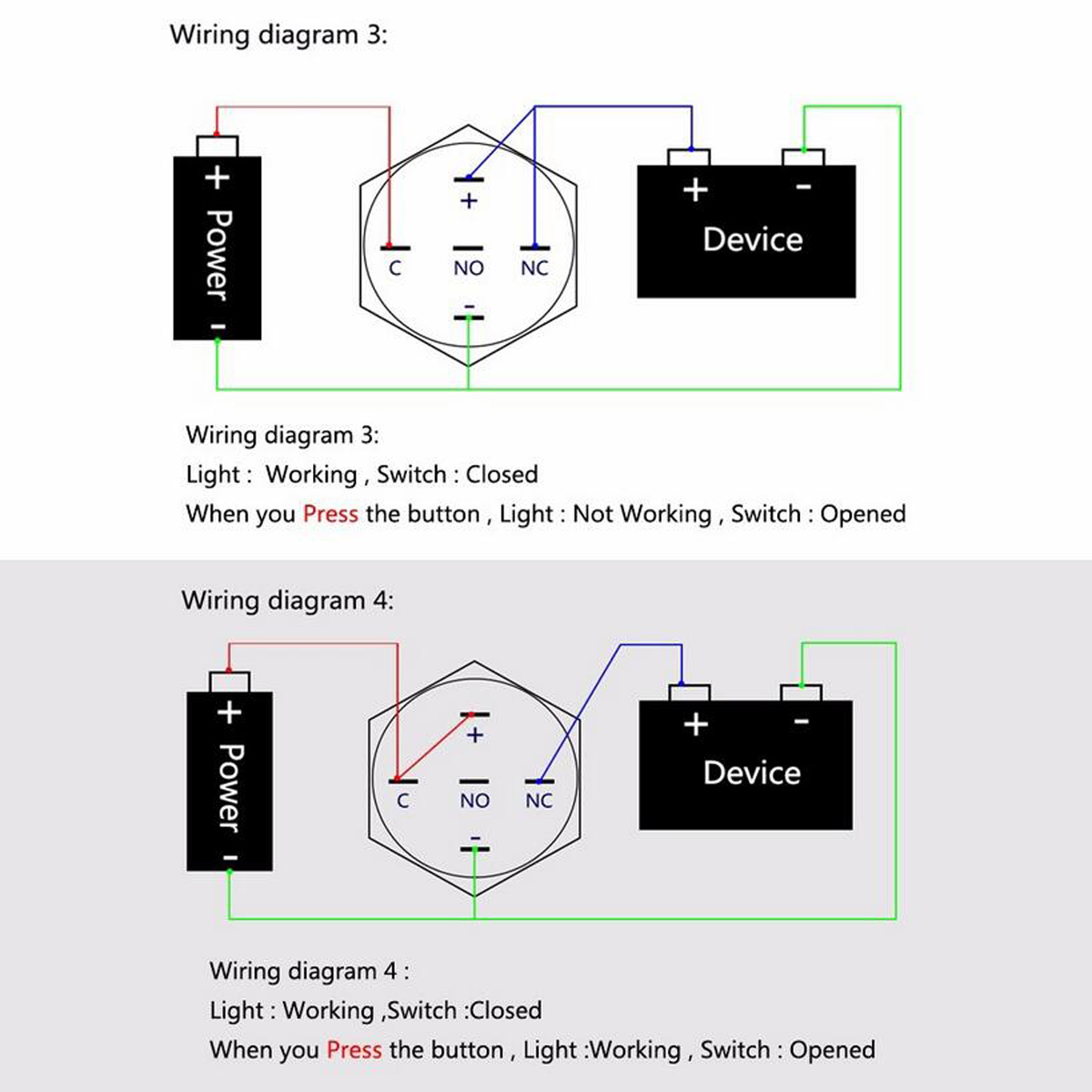
New 16mm 12v 24v 36v 5a Led Horn Push Button Dashboard
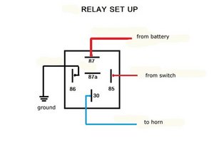
Push button horn wiring diagram. So pressing the button simply completes the circuit from the center wire a through the button to the common portion of the column b. For the most common horn button installation the center wire is con nected to the center connector a on the button. Does the horn work by grounding the circuit to make the horn sound. I have tried to find a wiring diagram for this circuit but have been unsuccessful. Is it possible to connect the horn wire to a simple button. It is no longer an option of whether to replace the electrical horn.
Push button horn wiring diagram wiring diagram is a simplified adequate pictorial representation of an electrical circuit. Center wire is connected to the grounded or common portion of the steering column. You press it in and it clicks on and when you press it. It shows the components of the circuit as simplified shapes and the talent and signal associates in the middle of the devices. For most up dates and latest news about new push button horn wiring diagram shots please kindly follow us on tweets path instagram and google plus or you mark this page on book mark area we attempt to provide you with up date periodically with all new and fresh images like your exploring and find the ideal for you. A wiring diagram usually gives recommendation practically the relative point of view and settlement of devices and terminals upon the devices to urge on in building or servicing the device.
We send a card with these diagram with every order. I looked at your profile and apparently you have had this vehicle since 2008 or longer. Todays anti theft systems are tightly integrated to the horns. Chance are good your horn will honk when you press it. Volvov70 september 24 2016 302am 2. For those wondering what this mean a latching button act like a toggle switch.


