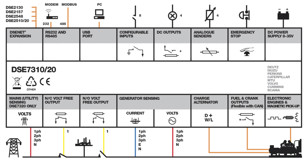
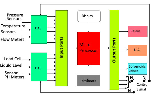
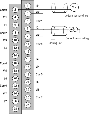
Ina process plant onoff control is done through the plc or dcs. A diagram that uses lines to represent the wires and symbols to represent components.

Programmable Logic Controller Wikipedia
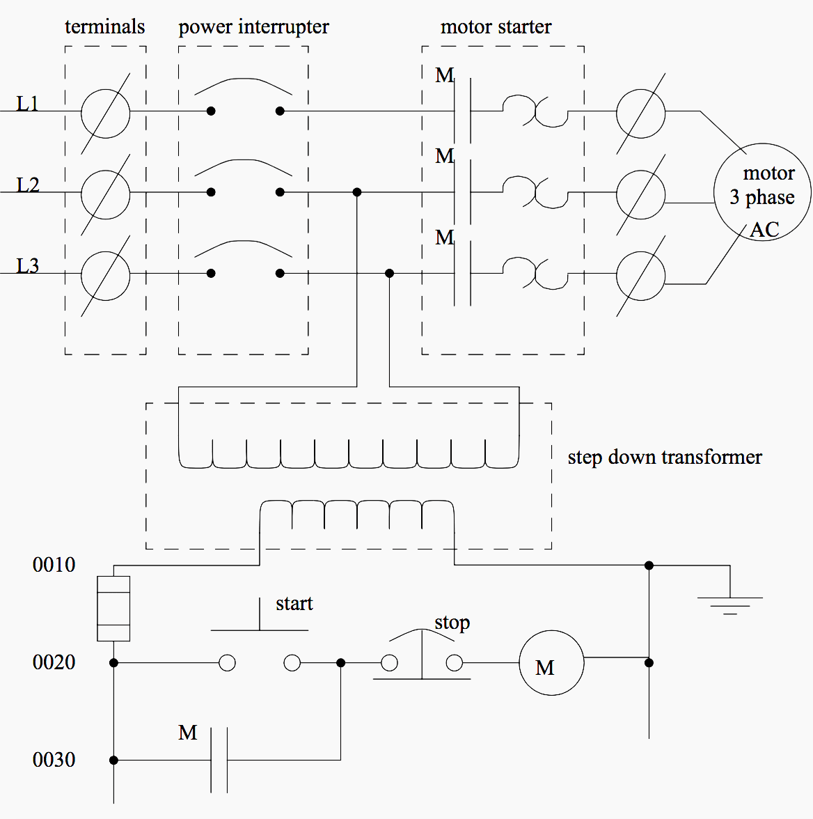
Plc wiring diagram guide pdf. Figure 5 below shows a schematic diagram for a plc based motor control system similar to the previous motor control example. A wiring diagram is a streamlined conventional pictorial depiction of an electrical circuit. Electrician circuit drawings and wiring diagrams youth explore trades skills 3 pictorial diagram. S bharadwaj reddy december 16 2018 march 21 2019. Chapter 1 automating with a plc b 1 11 introduction b 1 12 areas of application of a plc b 2 13 basic design of a plc b 5 14 the new plc standard en 61131 iec 61131 b 8 chapter 2 fundamentals b 11 21 the decimal number system b 11 22 the binary number system b 11 23 the bcd code b 13. But it does tend to become more complex.
A wiring diagram is a streamlined traditional pictorial depiction of an electric circuit. This figure shows the e stop wired to cutoff power to all of the devices in the circuit including the plc. A diagram that represents the elements of a system using abstract graphic drawings or realistic pictures. The operation of pressing a pushbutton corresponds. Assortment of plc panel wiring diagram pdf. Collection of plc wiring diagram guide.
Plc wiring diagram guide pdf. Assortment of plc control panel wiring diagram pdf. Plc digital signals wiring techniques. It shows the elements of the circuit as streamlined shapes as well as the power as well as signal connections in between the tools. When including a plc in the ladder diagram still remains. The below figure is an overview of one discretedigital onoff circuit showing the entire process from the power supply.
Wiring fixed contact wiring wiring circuit closed circuit open wiring contact wiring spring spring spring before button is pressed in return position after button is pressed in operating position spring circuit open note 1 actuate here means to force operation from normal state of rest. A wiring diagram is a simplified conventional photographic representation of an electric circuit. It reveals the components of the circuit as streamlined shapes and the power and also signal connections in between the tools. It shows the parts of the circuit as streamlined shapes and also the power as well as signal connections in between the devices. Wiring diagram book a1 15 b1 b2 16 18 b3 a2 b1 b3 15 supply voltage 16 18 l m h 2 levels b2 l1 f u 1 460 v f u 2 l2 l3 gnd h1 h3 h2 h4 f u 3 x1a f u 4 f u 5 x2a r power on optional x1 x2115 v 230 v h1 h3 h2 h4 optional connection electrostatically shielded transformer f u 6 off on m l1 l2 1 2 stop ol m start 3 start start fiber optic.


.png)


