This connection should not be used with reversing motors. Te02 phase angle relay specifications.

Nf 8482 3 Phase Electrical Wiring Diagram In Uae
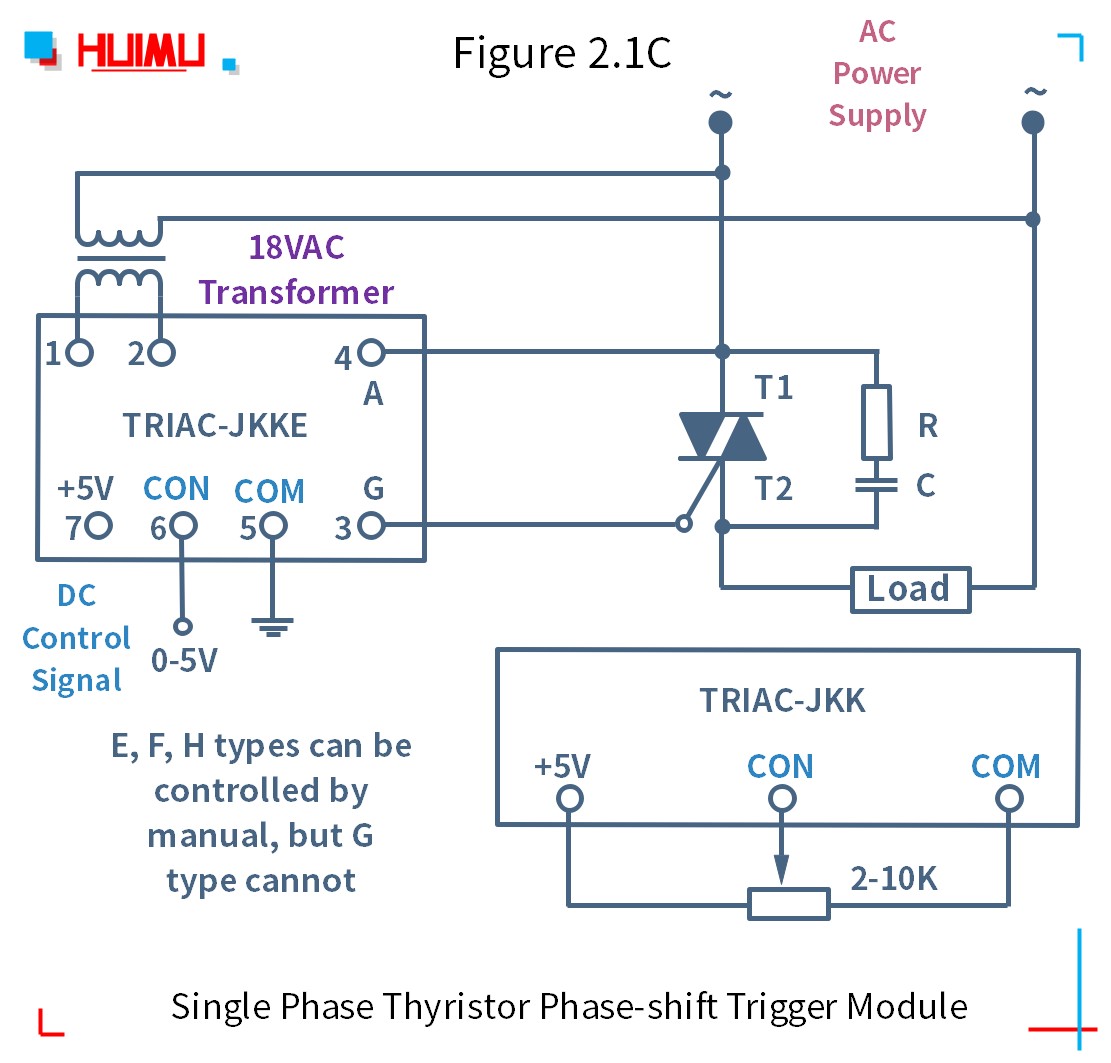
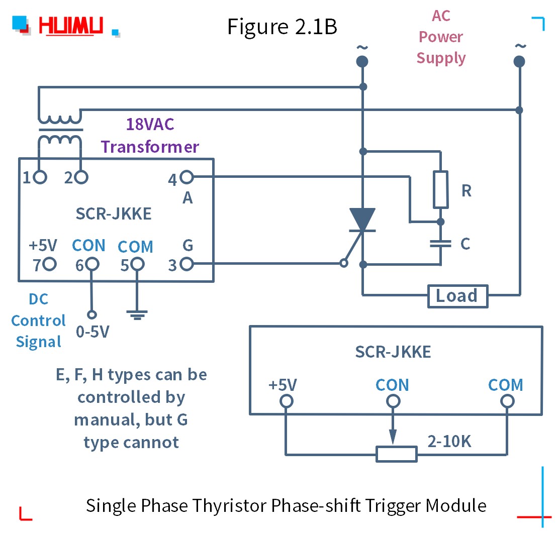
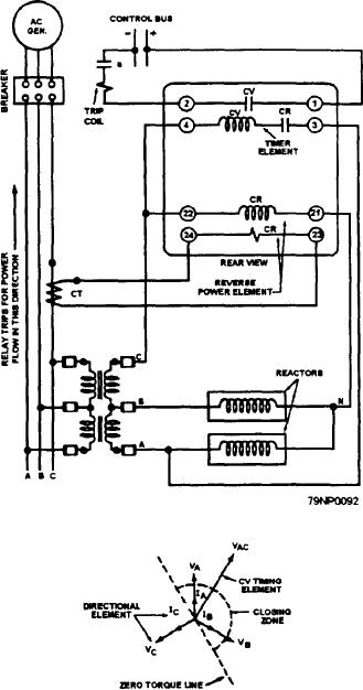
Phase angle relay wiring diagram. You cant determine phase rotation with a phasor diagram unless you know the one universal rule in the relay testing world. When this is done care. The video below shows you how the waveforms and phasors inter relate. Connection diagram to connection diagrams vary for other voltages ct required where flc exceeds ioa use one relay per pump. Single phase 230v 20 three phase. Three lpc series phase angle power controllers or one three phase lpc series power controller can be used to control all three phases of a wye with neutral or delta configured three phase load.
M1 page number technical specification. With the relay connected directly to the motor the total feed lines are monitored. Single phase motors controls 12 1 hp crc qd relay 282 40 5015 sixth digit depends on hp control box wiring diagrams gnd green cap capacitor b l1 b main y r start l2 l1 motor leads line leads orange qd relay black yellow red blue gnd green gnd green gnd green start capacitor run capacitor cap b l1 qd relay. Knowing the sequence of operation for this type of starting relay can help you diagnose confirm or rule out certain service problems. Yes although the wiring is slightly less straightforward than with a standard onoff ac multiphase power controller. 75 pw205 pw205 20 25 15 185.
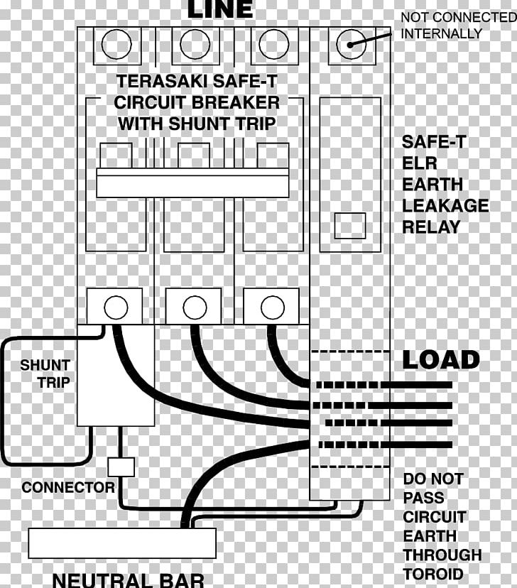
400v 20 525v 20 2va automatic activated by pushbutton calibrated phase angle and current 10 2 seconds delay calibrated voltage 10 2 seconds delay calibrated current 20 1 second delay 3 starts per 15 minutes maximum te03 adjustable 15 minutes to 24 hours. Calibrated phase angle and current 10 2 seconds delay. Know your potential starting relays this website requires certain cookies to work and uses other cookies to help you have the best experience. 230vac 20 three phase. With a nonreversing starter interfacing phase failure relays with shunt trip circuit breakers phase failure relays are often used to control a shunt trip circuit breaker. Pump and motor protection phase angle relays te series phase angle and pump protection relays te0203 pump protection relay specifications supply voltage.
All phasors rotate counter clockwise. Calibrated voltage 10 2 seconds delay. Net price all prices exclude vat unless stated otherwise. Automatic activated by pushbutton. Note due to wrong connection done the above diagram is update in the above diagram i shown the complete method of wiring or connection of phase failure relay diagram with circuit breaker cont actor overload relay push button switches and electric motor however lets talk about this step by step.
