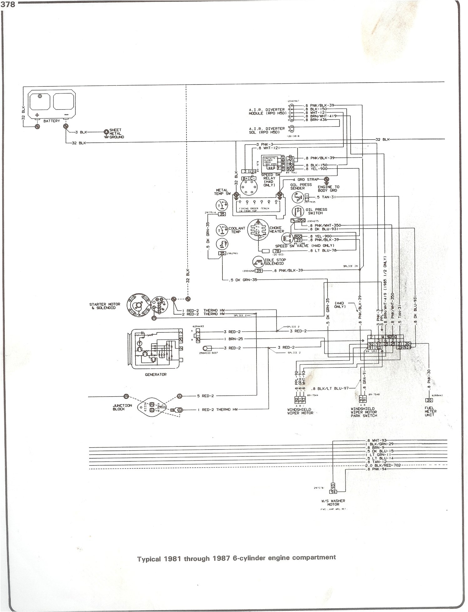
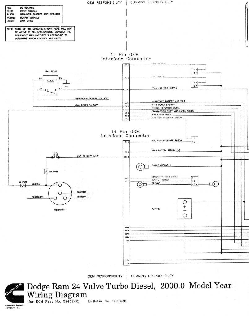
1 wire alternator diagram carlplant size. For obtaining additional wiring installation information see heavy duty application manuals or contact a remy inc.

Mercedes C350 Fuse Box Diagram Auto Electrical Wiring Diagram
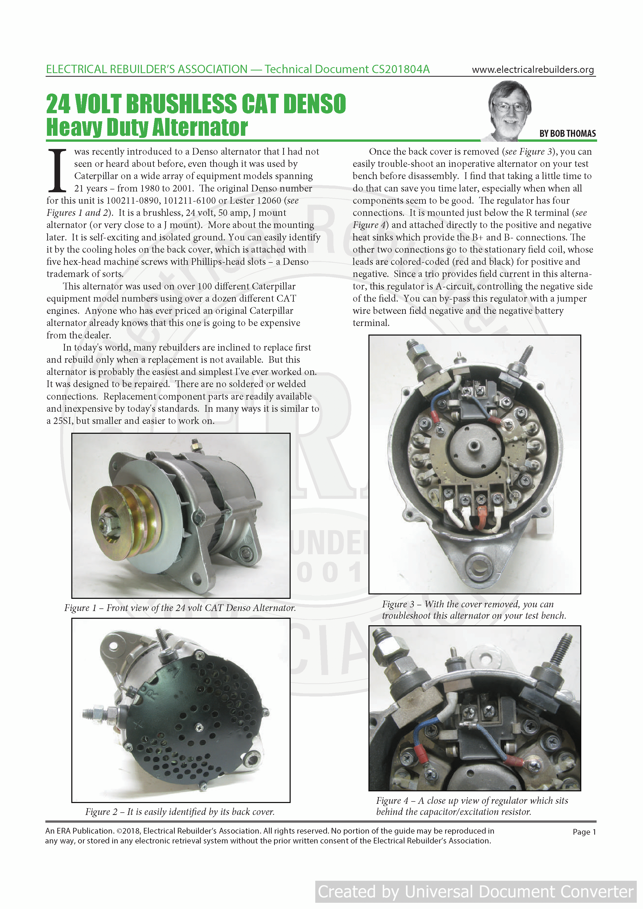
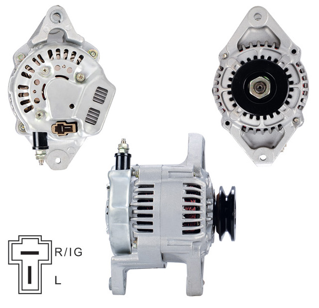
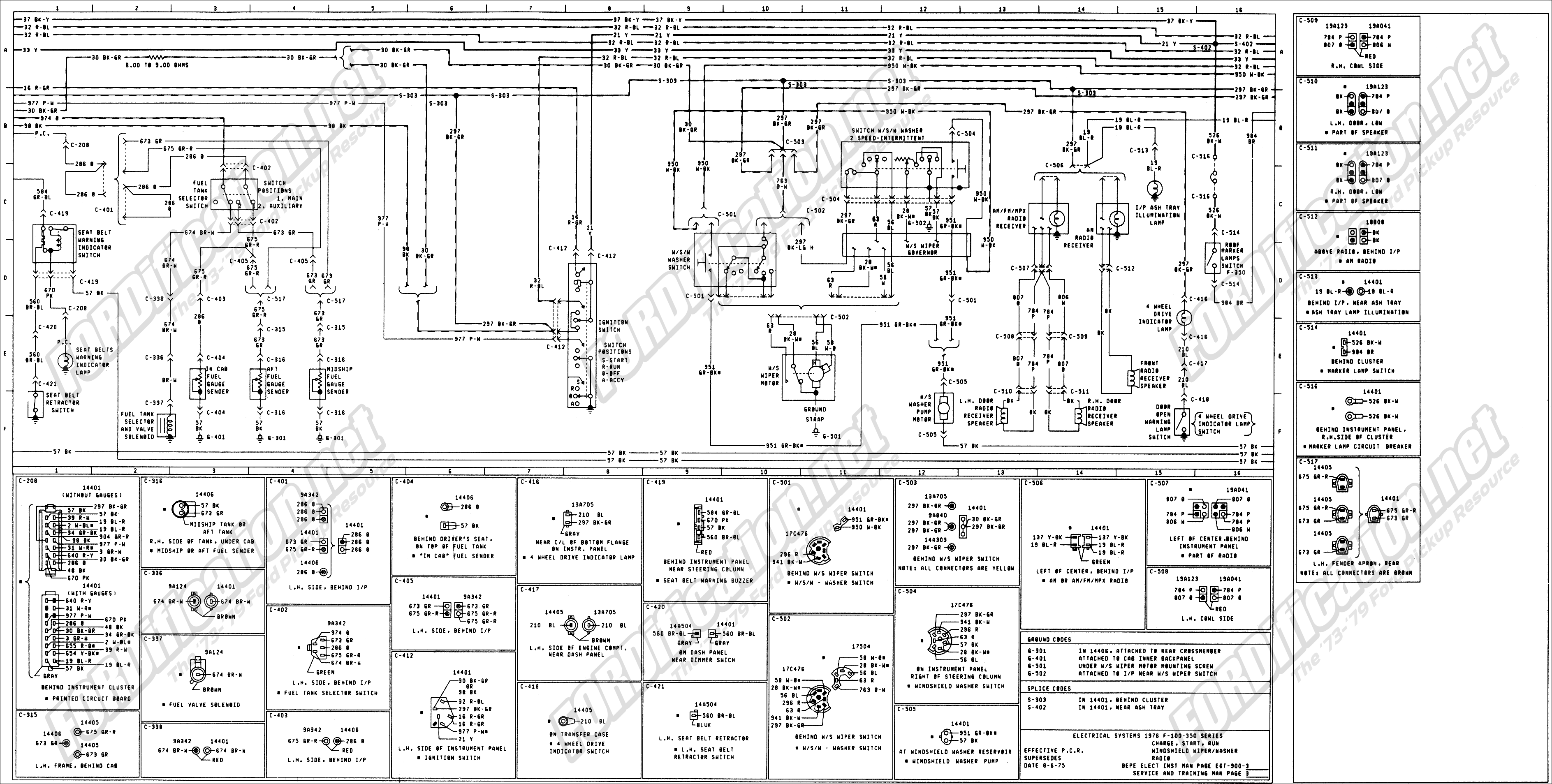
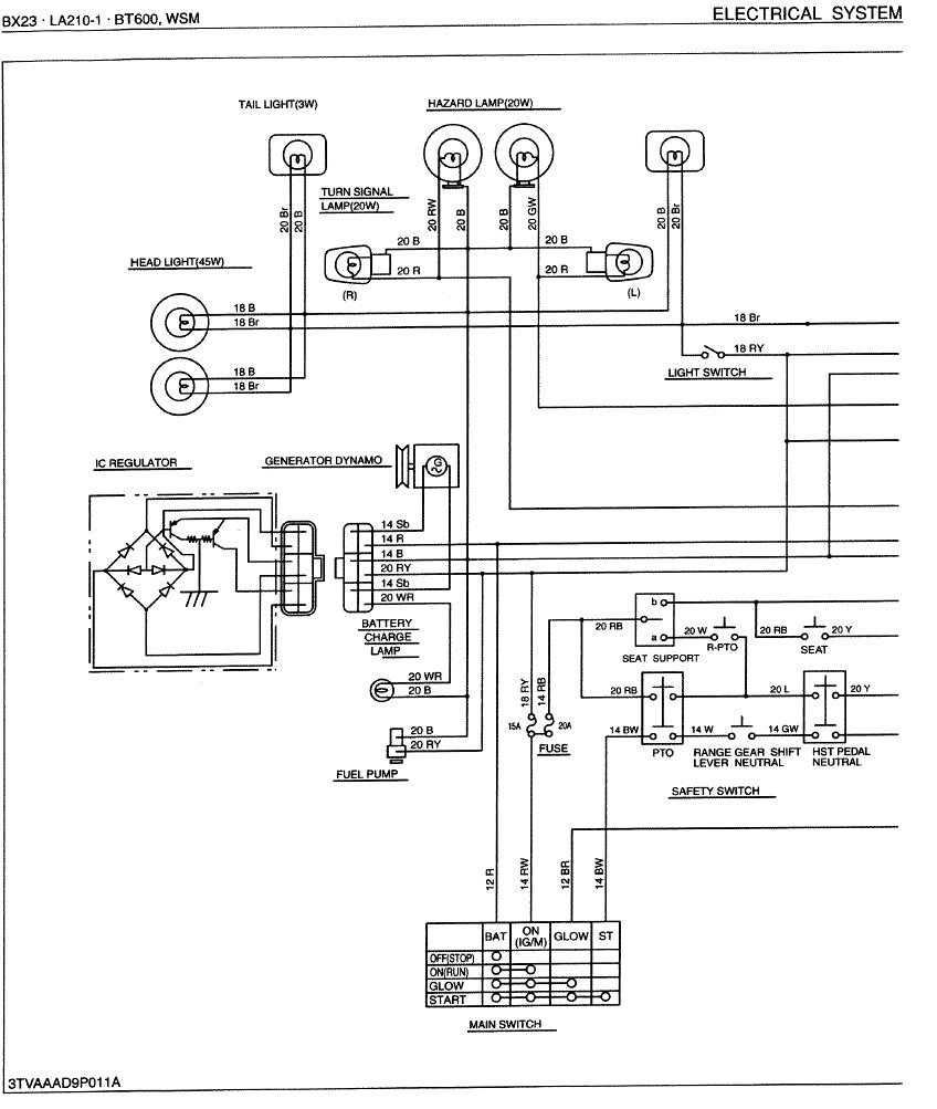
Nikko alternator wiring diagram. Right here are some of the leading drawings we get from various sources we wish these pictures will work to you and also ideally extremely appropriate to what you want about the 1 wire alternator wiring diagram is. It shows the components of the circuit as simplified shapes and the capacity and signal friends in the middle of the devices. Types alternator with brushes brushless models. 10581 alternator 24v 40a iref nikko aftermarket price. B is the alternator output wire that supplies current to the battery. 24v system alternator output b terminal to battery positive terminal at full output.
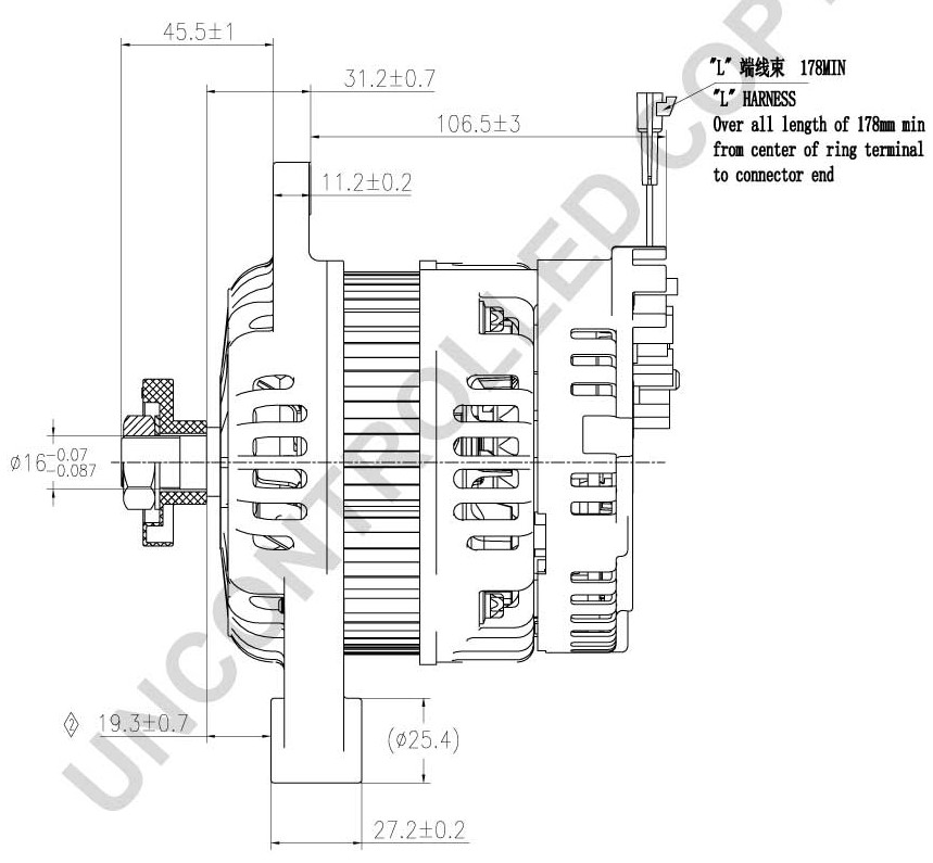
Follow engine or vehicle manufacturers instructions for removing the old alternator from the. If a new regulator is being installed along with the alternator complete its wiring. 800 x 600 px source. 16077 john deere excavators 135c 225clc forester 200lc hitachi new holland excavators e130 e200sr. Features a line up of models to cope with a wide range of applications. Tach wire if needed and other necessary wiring.
If the voltage rises above or falls below 12 volts the alternators internal voltage increases or reduces power output to. S is used by the regulator to monitor charging voltage at the battery. Nikko alternator wiring diagram wiring diagram is a simplified customary pictorial representation of an electrical circuit. Connect alternator to balmar regulator wiring harness as indicated in wiring diagram included on page 12. Ig is the ignition input that turns on the alternatorregulator assembly. The alternators positive and ground cables should be sized according to the chart on page 3.
If you have a two wired alternator place the metal sensor on the end of the black wire onto the metal part of the vehicle. If you are able to look at a manufacturers diagram of the alternators connectors the wire that slides over pin 1 of the alternator leads to the positive connection on the vehicles battery and senses voltage. An unpainted bolt is a good example. Products of high quality and stable mechanism are available and they can fulfill diversified needs of customers. It leads to the alternator and connects to the terminal labeled b or bat place the sensor on the end of the red wire from the multimeter onto the metal alternator terminal. Understanding the alternator four wires connect the alternator to the rest of the charging system.

