Ariadni toggler dimmer. Search the lutron archive of wiring diagrams.
Wsx D Pdt Dual Technology Occupancy Sensor Switch W
Dvstv wh wiring diagram. Sold in contractor packaging. Carefully push wires into wallbox allowing room for the control back cover. 0 10 v ballastdriver white white red red red white blue. 010 v is quickly becoming one of the more popular dimming technologies with wired occupancy sensors for v. Find your product or system name. Wiring diagram using relay figure c1.
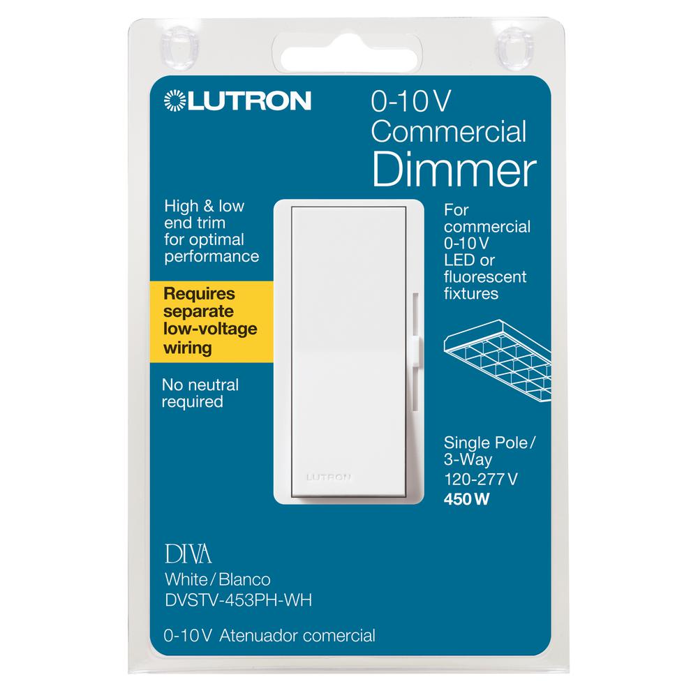
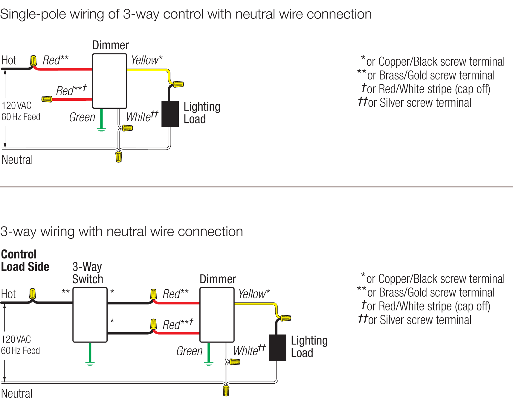
Lutron diva dvstv v dimmer for fluorescent and led the lutron diva dvstv is a v dimmer that easily lutron dvstv v installation instructions. Specify the product or system. Mount control into wallbox using screws provided. Wiring diagrams dvstv and dvscstv single pole wiring 3 way wiring copper bal ck screw termni al brass godl screw termni al green screw terminal. Lutron diva dvstv wh spec sheet author. Invest in a lutron diva dvstv wh 0 10v dimmer switch for 3 way applications.
Wiring diagrams dimming with onoff control wiring diagram using relay 0 10 v ballastdriver white white red red red white blue gray graygray red red purple purple purple blue white black black 0 10 v ballastdriver neutral hot live 120 230 277 347 v 50 60 hz pp 120h 230h 277h 347h class 2 only black black. Package contains no instructions. 0 10 v ballastdriver white white red red red white blue. Do not install the relay in the same wallbox as the low voltage control. Refer to the wiring sheet included with the relay for more information. To find a diagram for a specific product or system please use the drop down menus below.
Wire controls according to the appropriate wiring diagram shown in the wiring section of this sheet and on the ballast. Refer to the wiring sheet included with the relay for more information. Wiring diagram using relay figure c1. 010 v control link controls third party fixtures dvstv wires as single pole add color suffix to model example. Download instructions and wiring diagram here. Dimming with onoff control via relay connect the control as shown in figure c2.
Do not install the relay in the same wallbox as the low voltage control. Units must be mounted vertically. Model number operating voltage wiring load switching capacity 010 v sink capacity dvstv xx 2 120 277 v single pole 3 way 5 8 a 50 ma dvstv 453ph wh 1 dvstv 453ph wh c 1 3 120 277 v single pole 3 way 5 450 w 375 a 120 v 162 a 277 v 50 ma dvtv xx 2 dvsctv yy 4 24 v single pole only 0 a6 30 ma model numbers. Dvstv wh dvtv wh wh white iv ivory al almond la light almond gr gray br brown bl black. Dvstv wh dvtv wh add color suffix to v control wallbox controls b 6 wiring diagrams dvstv and. Dimming with onoff control via relay connect the control as shown in figure c2.
