We didnt make them so popular our customers did. Typical wiring diagrams in order to consistently bring you the highest quality full featured products we reserve the right to change our specifications and designs at any time.

5t 15t 12t 24t Time Switches Fw Murphy Production
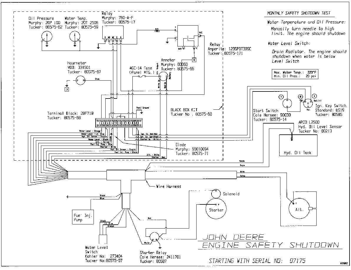
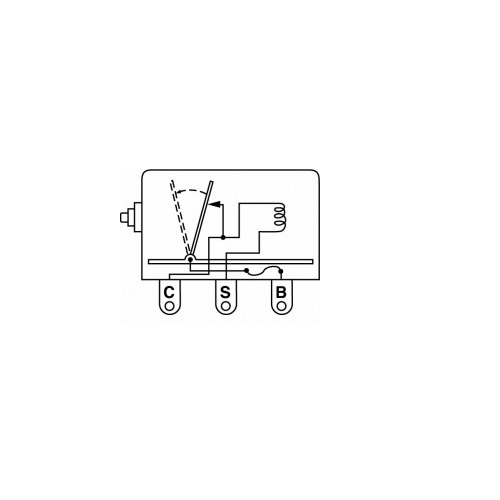
Murphy switch wiring diagram. Typical wiring diagram with ms2100 tattletale typical wiring with 518e models. It will keep power on from the nc terminal to your run circuit unless you have a safety condition on oil pressure or coolant temperature. Terminal on magnetic switch and coil c no o 518aph nc b o o at inllne egs21p. Hdrgagessmalljpg fw murphy is known for its gauges and theres a good reason why. Rcsistor or resjswr must be nc. View and download murphy tattletale wir 97020b wiring instruction online.
We just make them solid and reliable every time. Closing off the fuel or air supply. Murphy wd 03061b wiring diagram wd300 series panels wd300 wd300lv 117ph tattletale magnetic switch with mechanical swichgages emergency stop push button. Murphy will hook up both ends customer will hook up both ends. Tattletale wir 97020b switch pdf manual download. Typical wiring diagrams.
117 117ph tattletale ms2100 tattletale 518ph 760a 761aph. For electric motor application various magnetic switches are available to operate the motor starter holding coil directly or in conjunction with appropriate murphy transformer relay assembly. Typical wiring diagrams figure 2 shows a closed loop circuit with normally open murphy swichgage and v. Theyre highly accurate and long lasting. Download this article as a pdf 00 02 0257. Murphy and customer wired will hook up this end methods of engine shutdown for diesel and spark ignition engine arc shown.
Theyre durable and dependable. This is a basic energize to run panel. Select appropriate circuit and wire accordingly. Figure 2 shows a closed loop circuit with normally open murphy swichgage instruments and normally closed switches alignment and v belt switches etc. This is not a closed loop circuit. Start switch alternator to magnetic sensor alternator tach terminal or signal generator b energized to run pb128s stop switch starter s b exciter r fuel valve typical wiring diagram with 760a and 761aph g no r nc sw1 sw2 b 518ph jumper b sig grd distributor ignition coil fuel valve rack pull solenoid rp2300 series shown.
Typical wiring diagram with 117117ph magnetic switch. Magnetic switches and tattletale annunciators can make or break circuits for these engines. Shows a jumper installed between sw1 and sw2 swichgage instruments are normally open. Magnetic switches and tattletale annunciators.
