Assortment of magnetic door contact wiring diagram. Click edit in the lower right and provide a friendly name for the device.

Door Contact Wiring Amp Eol In Series Diynot Forums Sc 1 St
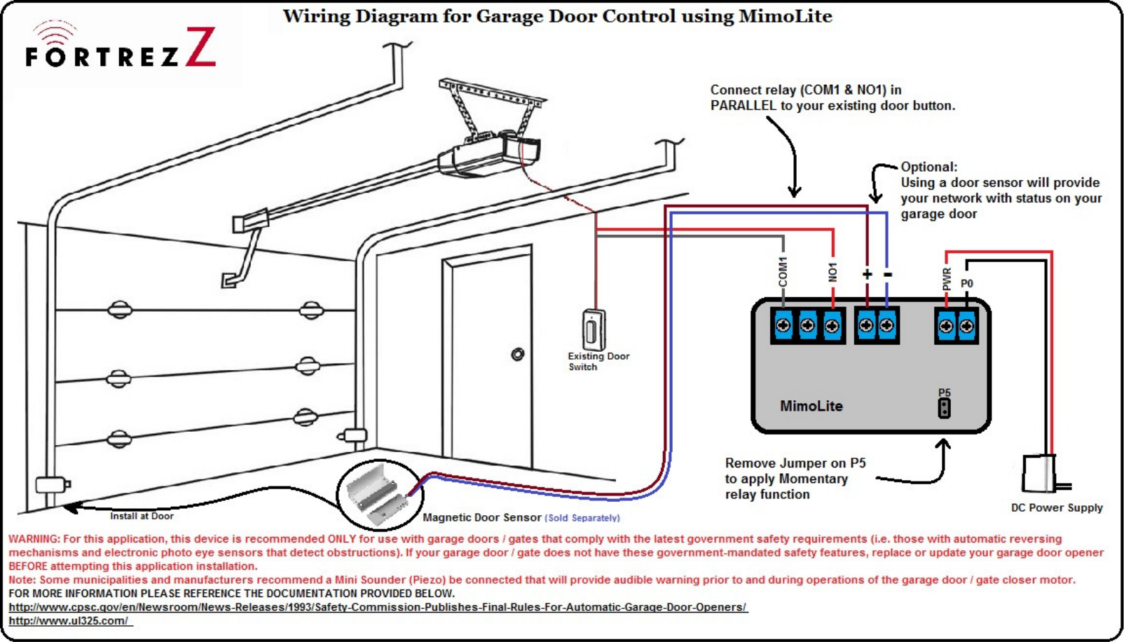
Mimolite wiring diagram. Mimolite likely only has enough residual power to send to the first node in association group 3. Wiring diagram for garage door control using mimolite connect relay comi noi in parallel to your existing door button. We can trigger this behavior with z wave commands and the mimolite as well as the original garage door button. Using a door sensor will provide your network with status on your garage door exist ing itch mimolite dc power supply remove jumper on p5 to apply momentary. Either way the components youll need are. The mimolite will show up as a non secured switch binary made by fortrezz llc.
In our case this is switch 002. Mimolite wiring diagram for apollo gate opener. Mimolite wiring diagram for garage door application. Diagram is in the file section of the mimolite product. Mimo2 installation instructions for smartthings. Mimolite installation guide for smartthings.
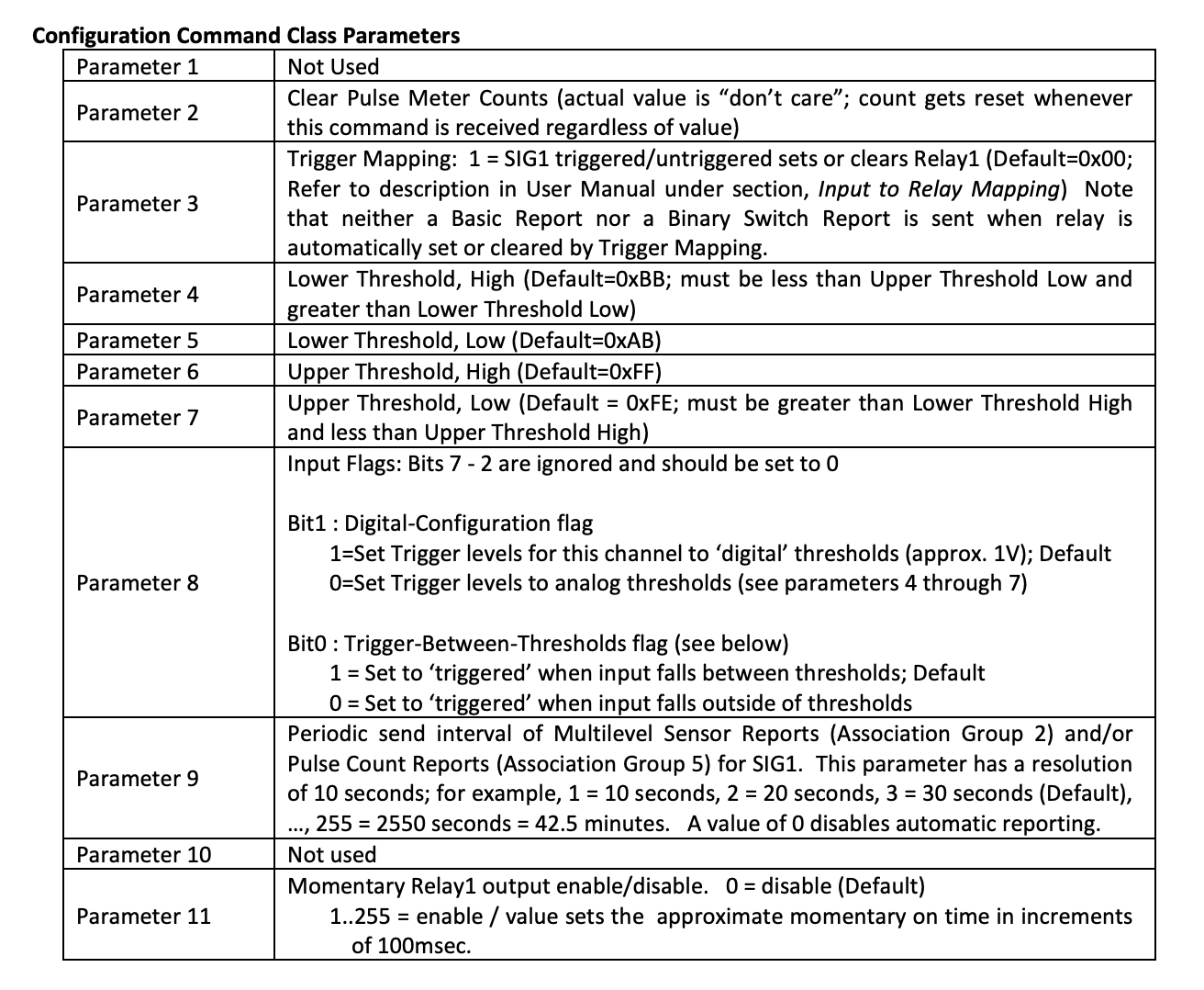
If unlike me you already know what youre doing then fortrezz the company behind mimolite actually has a wiring diagram on their site. Yes see for example one wiring diagram on how one of our customers did this. Mimolite installation instructions for vera controllers. Press the back arrow on the lyric until you see switches. For example if ztrigger between thresholds is enabled then. Mimo config tool for advanced users input voltage mapping.
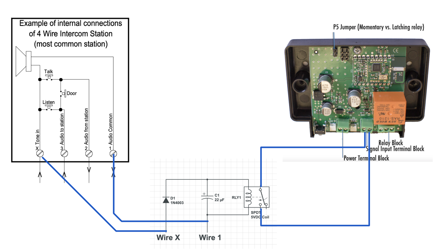
A wiring diagram is a streamlined traditional pictorial depiction of an electric circuit. Fortrezz mimolite wireless interfacebridge module technical appendix pdf fortrezz wiring diagram for garage door control using mimolite pdf fortrezz mimolite installation instructions for vera controllers pdf fortrezz mimolite and homeseer hs2 binary sensor reporting application note pdf. You must select the desired relay operation before you add the mimolite or mimo to your z wave network. How can i change relay operation from latched to momentary or the other way. It shows the components of the circuit as simplified shapes and the power and signal connections between the tools. Im almost ready to give up on thisbut before i do id be interested in knowing whether there is any fellow poster who actually got the mimolite to show the status of the garage door using the wiring diagram provided by the manufacturer at this link.
The diagrams to the right show the triggering ranges based on which way the input voltage is changing. Mimolite wireless interfacebridge module. Press this option and then press the switch representing the mimolite.


