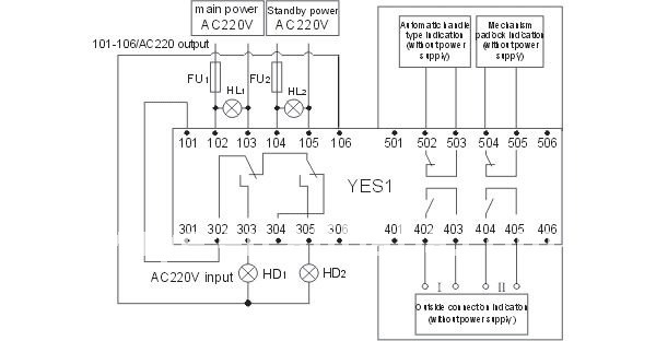
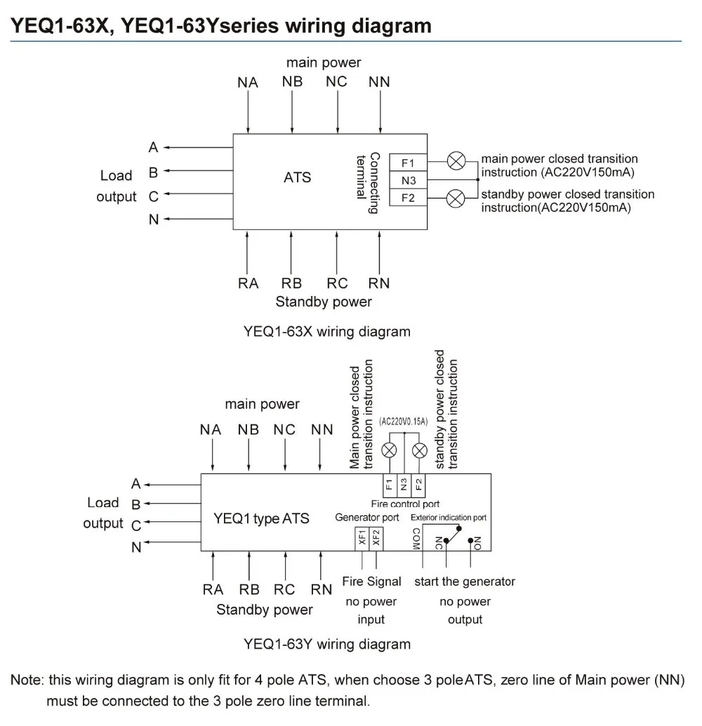
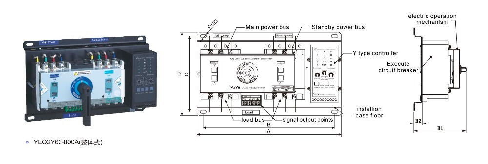
Manual changeover switch are mostly use in 2 types in which one have the move able knob and 2nd one the handle changeover switch. In fig 2 different connection and wiring diagrams are shown for a two pole single phase manual changeover switch.
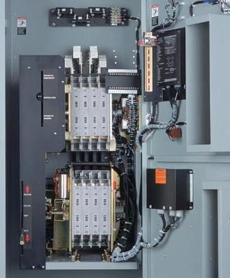
Understanding Transfer Switch Transition Types
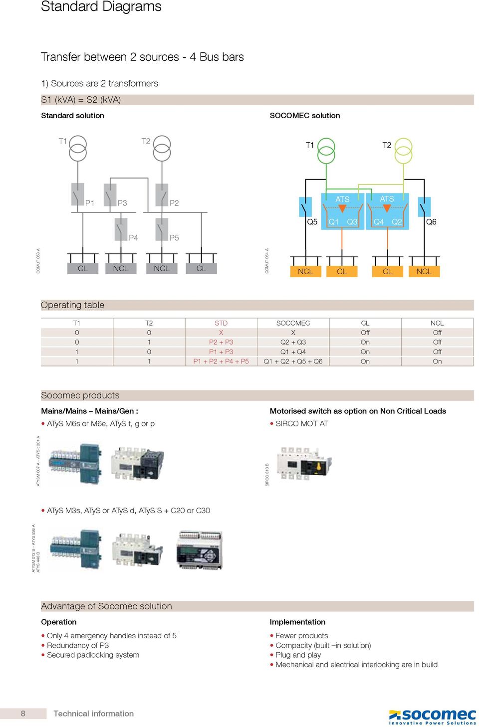
Socomec changeover switch wiring diagram. Manual cam transfer switches from 25 to 100 a como cs are manually operated multi pole transfer switches. Full range of manual remotely operated and automatic transfer switches from 16 to 6300 amps. Socomec changeover switches aim at ensuring ever more efficient ways to guarantee the continuity of distribution and therefore the rate of availability of your energy. This post i will shown the complete method of manual or handle change over switch the knob type manual changeover switch wiring same like handle change over switch and its just like a voltmeter sector switch. Subject to change without notice. Motorised switch cl ncl g q1 q2 ats automatic transfer switch protection arent shown on the following schemes summary.
They provide switching source inversion and changeover under load for two low voltage power circuits as well as safety isolation. The upper portion of the changeover switch is directly connected to the main power supply while the lower first and right connections slots are connected to the backup power supply like generator or inverter. Providing an unrivalled benchmark in source switching socomec is continuously innovating to ensure ever more efficient ways to guarantee the continuity of distribution and therefore the rate of availability of your energy. Motorised source changeover switch en step 1 1 2 installation step 3 step 6b 1. 1 8 h ˇ connections step 2 connecting the power section step 4 power terminal connections step 5 check installation and commissioning non contractual document. Step 6b step 6c manual operation padlocking mode.
