Electricity supply switches and of course locks. Use your existing electronic locks or kisi will help install new ones.

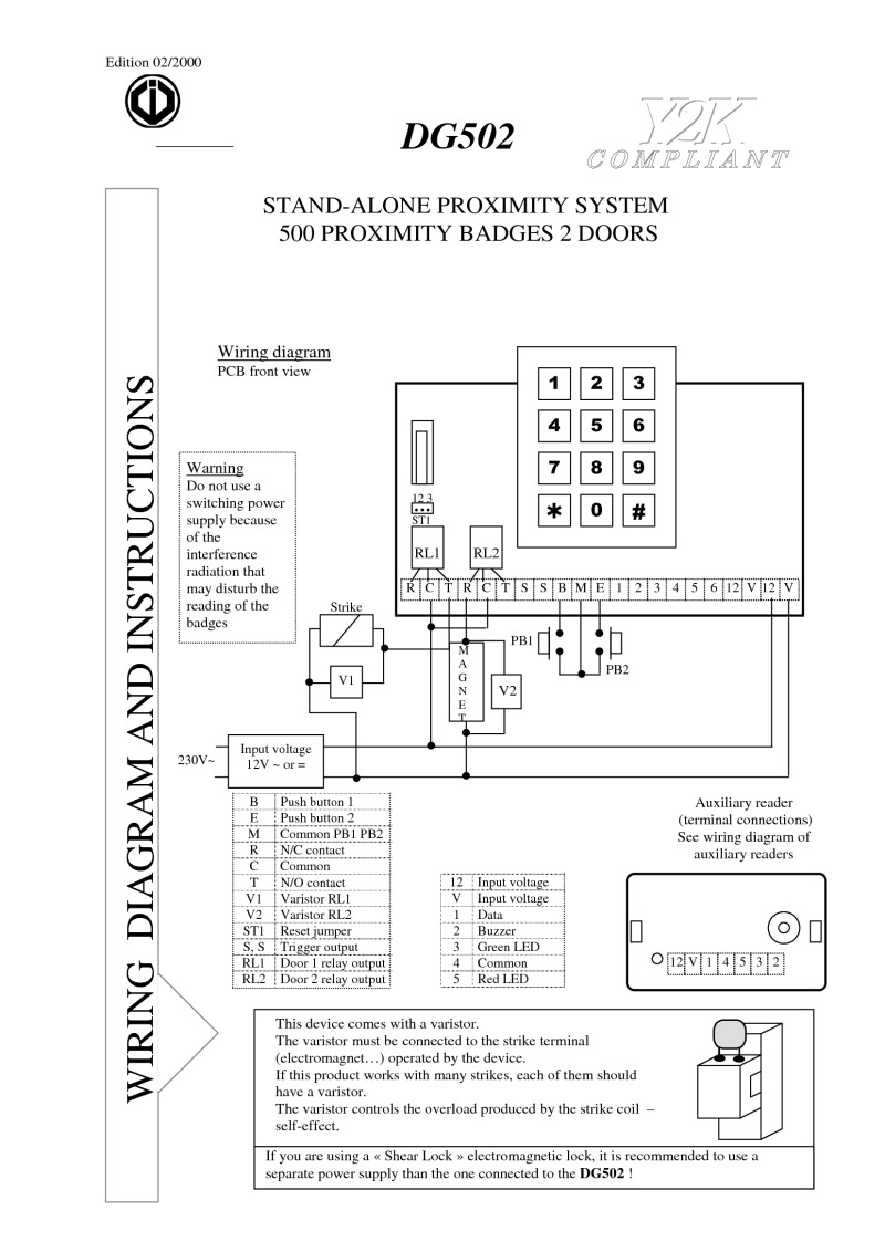
Vy 5082 Sd Control Wiring Diagram Free Diagram
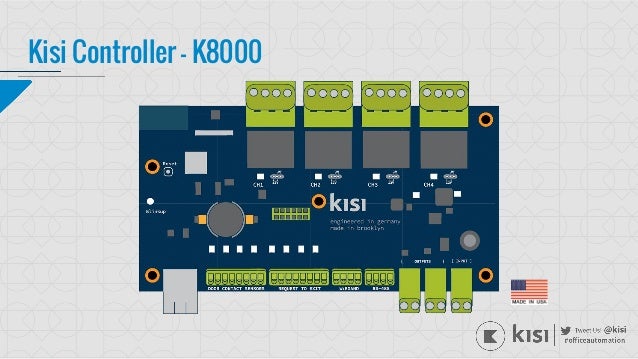
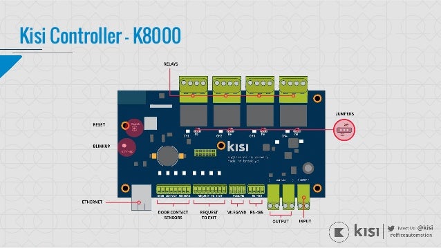
Kisi wiring diagram. 182 gauge wire home run from electronic lock to the it room. Upon shipment kisi will create your place account and associate your devices to your account for you. Which cat cable it is doesnt really matter for us your cabling company might have preferences depending on quality and distance. This diagram is a basic representation of how a kisi controller is wired to an electronic lock a maglock in the diagram though the principle is the exact same for a mortise lock. Kisi wiring diagram magnetic lock wiring diagram much like the door access control system diagram above the mag lock wiring diagram relies on a few simple basics. Push to exit button wiring guide.
Unlock your door in modern ways. Wiring diagrams for 3 way switches diagrams for 3 way switch circuits including. The neutral from the source is spliced through to the switch box using the white wire and in this diagram the white wire is capped with a wire nut. The k grip dual mold connectors offer sure grip and ergonomic shape for slip free installation and a union thats ultra slim for snag free cable routing in tight places. Wire one of the four door relays to the external power supply and the fail safe lock on your door. Be flexible with how different user groups can unlock the door.
Next you will need to run the negative wires to com common and run. The kisi pro reader works best with a wired cat5e or cat6 cable pulls from the future position of the swipe card reader to the it room. Since you will be wiring the relay as a dry contact you will start by wiring the relay to the power supply from com common and no normally open on the kisi relay to the gnd ground and in input of the power supply. This represents a change in the nec code that. With the light at the beginning middle and end a 3 way dimmer multiple lights controlling a receptacle and troubleshooting tips. There are project management suggestions wiring diagrams hardware specifications etc.
In this updated diagram 3 wire cable runs between the receptacle and switch and the red cable wire is used to carry the hot source to the switch. The controller receives authentication info from the reader and relays a signal to the power supply which then sends an impulse to the lock thus unlocking it. K series interconnects feature split pin rcas with silver tinned ofc wire for superior bass response and signal clarity. Magnetic locks also referred to as mag locks or maglocks for short rely on a constant flow of electricity to stay sealed. Upon installation please reach out to kisi to have one of us transfer your account to you and help get you on boarded. And can sometimes be labeled as led and led but are essentially the same.
If you are not completely familiar with installing rex buttons kisi highly recommends that you make your connections one pair at a time. Wiring diagram for swipe card reader.


