2242016 41745 pm. Domestic fire systems.

Ze 8381 End Line Resistor Wiring Diagram Download Diagram
Alarmsense base wiring diagram. A remote indicator can be connected to each base r remote led ve and. Alarmsense the alarmsense range of two wire detection and alarm products work via connection to a single pair of supply wires. A remote indicator can be connected to each base r remote led ve and l2 remote led ve. With sounder beacon base wall sounder beacon heat detector. The incoming and outgoing cables are connected to the same terminals l1 in ve line and l2 ve line. 3a alarmsense alarm relay wiring when used for sounders alarmsense base wiring connections to the alarmsense base part no.
Do not connect any field wiring to the l1 out terminal of the alarmsense base. A remote indicator can be connected to each base r remote led ve and l2 remote led ve. Alarmsense sounders visual indicators. 45681 244 are shown in fig. This benefits both the installer and the end user by making installation easier and quicker less expensive and more adaptable as you do not have to run separate sounder circuits. When powered and controlled by the alarmsense two wire fire panel this reliable technology takes all the complexity out of fire alarm system design leading to quicker less expensive and more flexible installations.
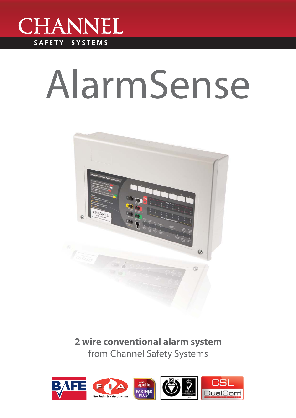
Cfp 2 8 zone alarmsense panels. Alarmsense detectors can only be mounted into the alarmsense base. Two wire fire systems. World class r ž solutions alarm c tec. The incoming and outgoing cables are connected to the same terminals l1 in ve line and l2 ve line. Soundersounder beacon base dil switch position.
C tec alarmsense cfp 2 wire diagram created date. Alarmsense manual call points. End of line resistor as recommended by the panel manufacturer. Fig 1 soundersounder beacon base alarmsense base wiring connections to the alarmsense base part no 45681 244 are shown in fig 4. The incoming and outgoing cables are connected to the same terminals l1 in ve line and l2 ve line. The base is used for installing detectors that do not require an integral sounder or sounder visual indicator.
Wiring connections to the alarmsense base part no 45681 244 are shown in fig 6. Sounder base manual call point c tec alarmsense cfp 2 wire diagram.


