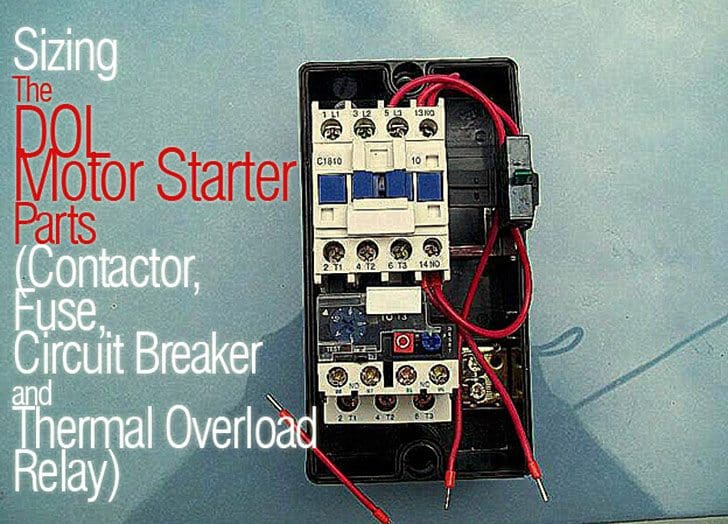
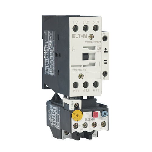
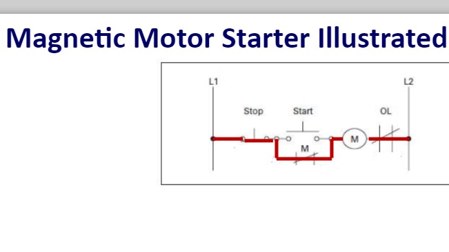
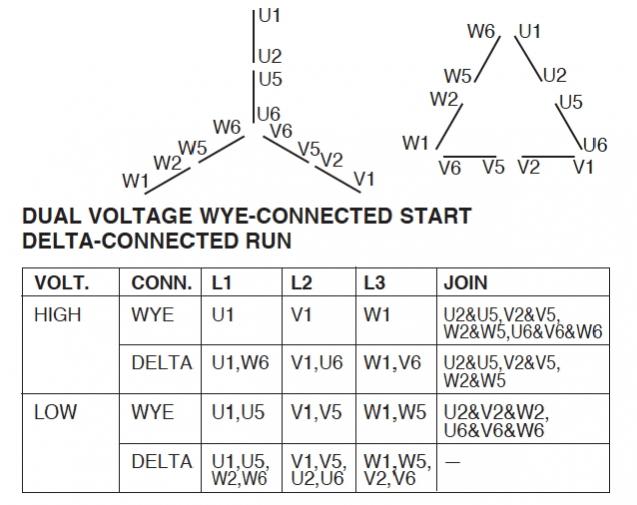
Iec motor starter wiring diagram architectural wiring diagrams show the approximate areas as well as interconnections of receptacles lighting and also long term electrical services in a structure. Iec motor starter wiring diagram what is a wiring diagram.
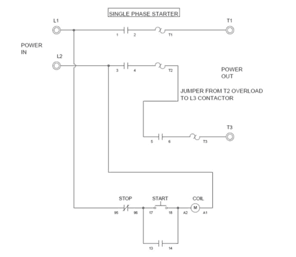
Single Phase Motor Protection Diagram Wiring Diagram
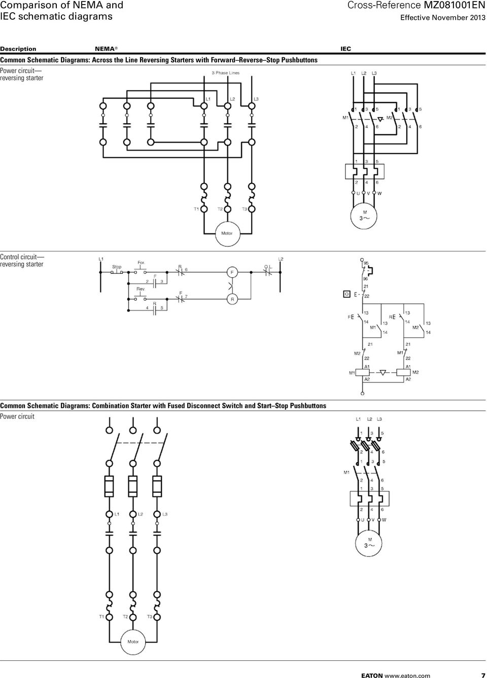
Iec motor starter wiring diagram. The purpose of this document is to provide a simple cross reference of common schematicwiring diagram symbols used throughout various parts of the world. 7192018 122208 pm. Iec schematic diagrams general. It shows the elements of the circuit as streamlined forms and the power and signal connections in between the tools. A wiring diagram is a simple visual representation from the physical connections and physical layout associated with an electrical system or circuit. September 19 2018 by larry a.
Interconnecting cable routes may be shown about where certain receptacles or components should get on a common circuit. Iec motor starter wiring diagram what is a wiring diagram. A wiring diagram is a simplified conventional photographic depiction of an electric circuit. Machine tool or a simple across the line motor starter the need to recognize and understand these. Overcurrent protection for 3 wire control circuits 11 ac manual starters and manual motor starting switches 12 class 2510 12 class 2511 and 2512 13 2 speed ac manual starters and iec motor protectors14 class 2512 and 2520 14 gv1gv3 14. Iec motor starter wiring diagrams springer controls co.
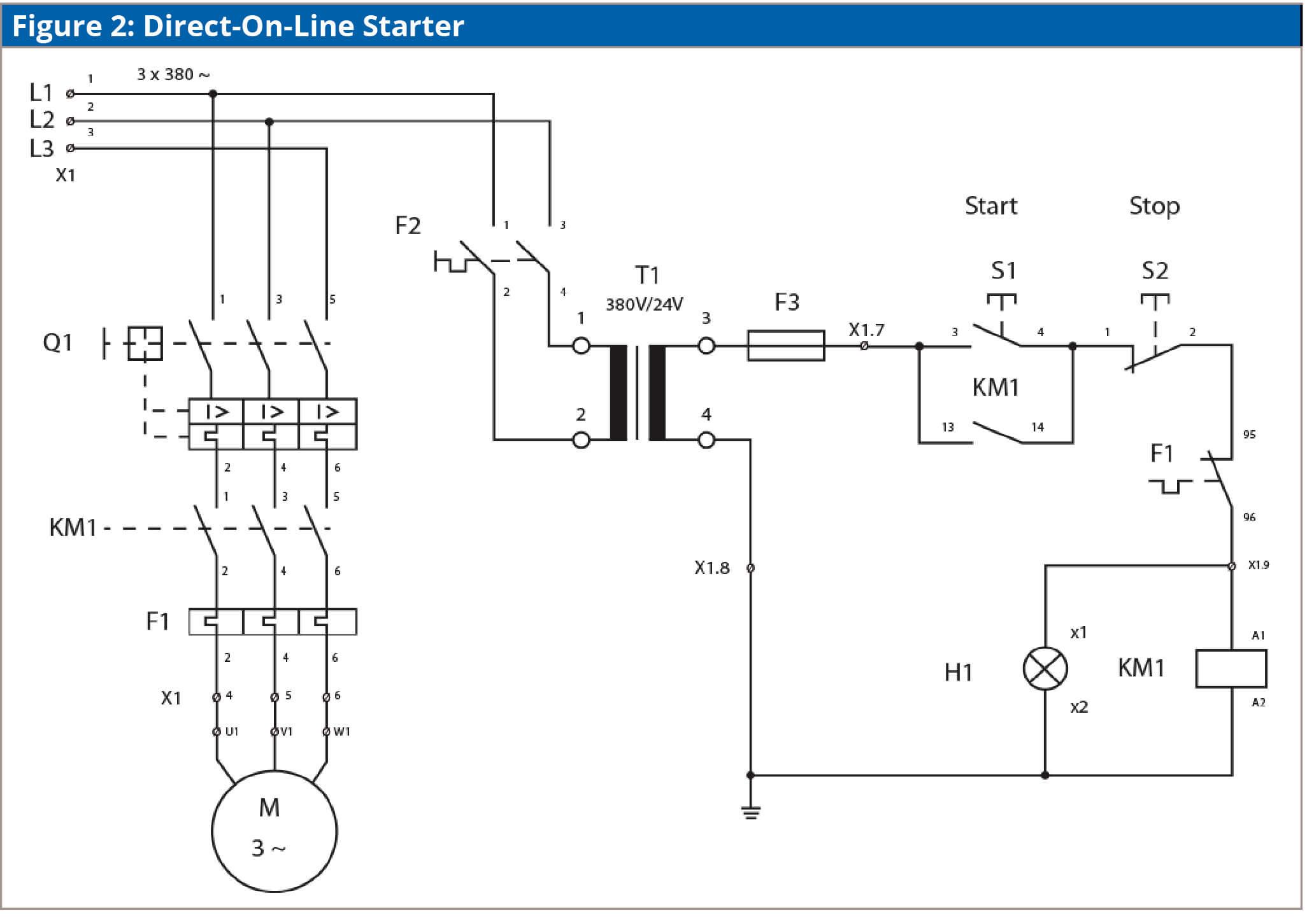
Wellborn assortment of iec motor starter wiring diagram. A wiring diagram is a simple visual representation from the physical connections and physical layout associated with an electrical system or circuit.
