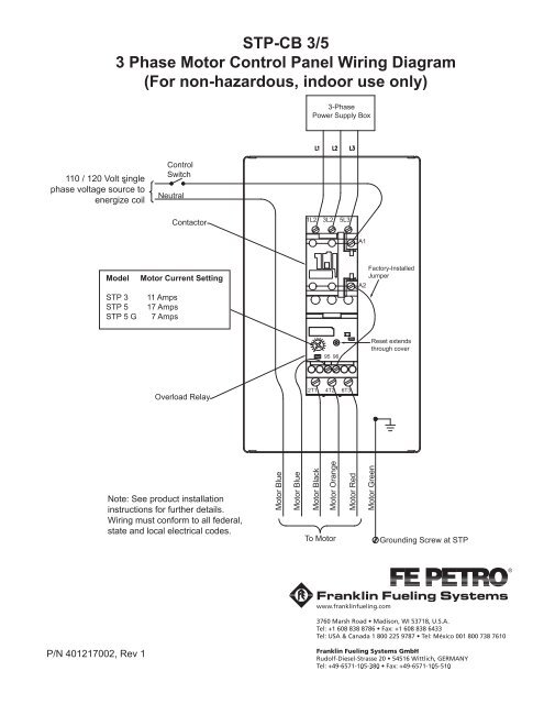
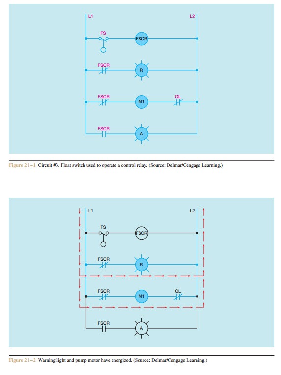
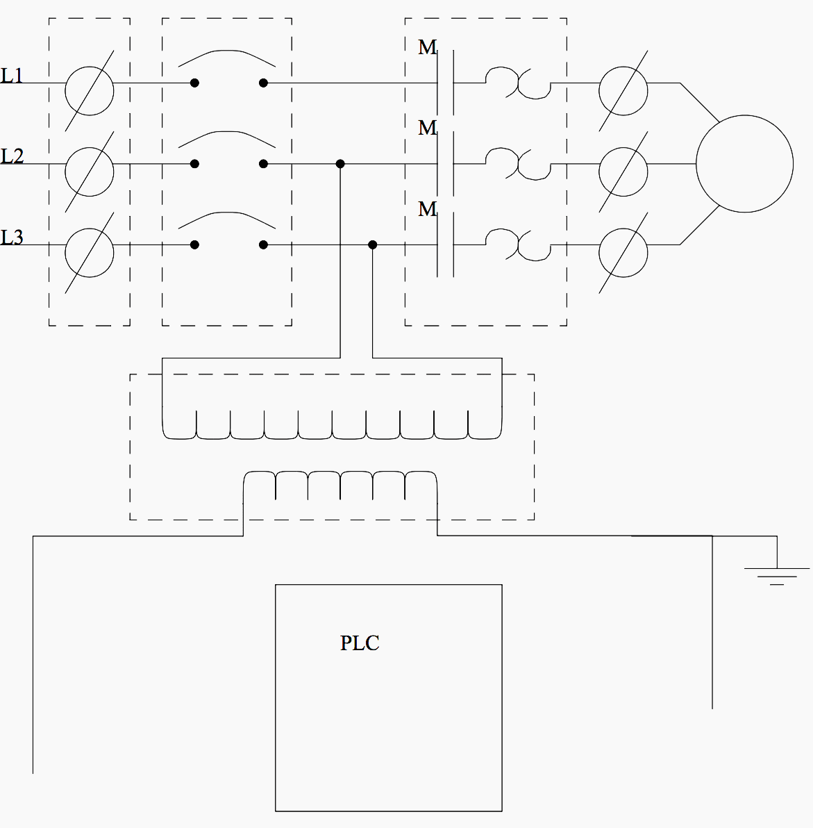
In an industrial setting a plc is not simply plugged into a wall socket. Lets go back and have a look at the control panel and try and figure out some of the connections by following a wiring diagram.
3 Phase Panel Board Wiring Diagram Lan1 Anb3 Vmbso De
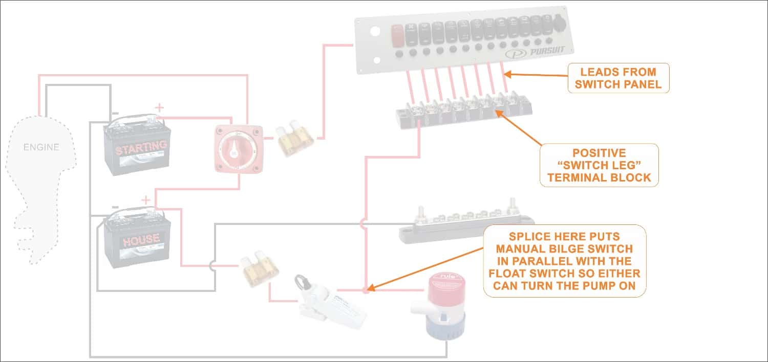
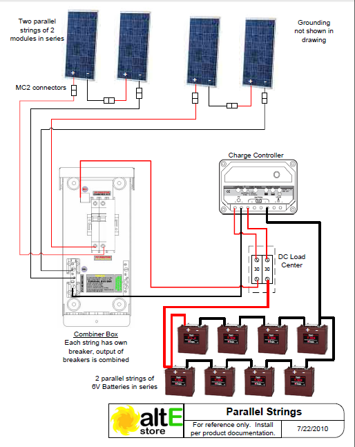
Panel wiring diagram. Electrical panel board wiring diagram wiring diagram is a simplified good enough pictorial representation of an electrical circuit. It demonstrates how the electrical wires are interconnected and can likewise reveal where components and also elements could be linked to the system. It is a 2 door control panel on the front of which we have some switches that are connected to the plc inputs and outputs. A wiring diagram is a basic graph of the physical connections as well as physical layout of an electrical system or circuit. This overview assumes that the electrical panel is installed on the wall of a utility area near where the main feeder wires come into the home and that all branch circuit wiring cables and conduit runs are already installed. This circuit breaker wiring diagram illustrates installing a 20 amp circuit breaker for a 240 volt circuit.
A neutral wire is not used in this circuit. The 122 gauge cable for this circuit includes 2 conductors and 1 ground. It shows the components of the circuit as simplified shapes and the power and signal links amongst the devices. The white wire is used for hot in this circuit and it is marked with black tape on both ends to identify it as such. The electrical design for each machine must include at least the following components. Transformers to step down ac supply voltages to lower levels.
As ive mentioned in the previous articles this is a control panel that is used for a system that turns wastewater into clean water. In a new home construction or a rewiring project the last step will be connecting all the wires to the circuit breaker box which is what this article describes. Electrical wiring diagrams of a plc panel. When and also the best ways to utilize a wiring diagram.


