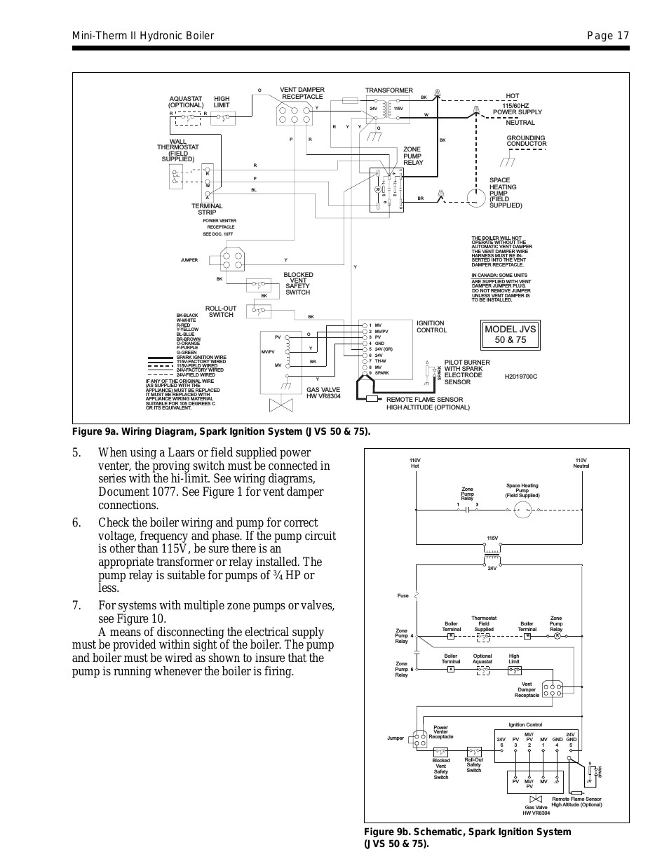
Variety of gvd 6 wiring diagram. The field controls gvd series gas vent damper is packaged in a single carton containing an assembled gvd instruction manual and a plug.

Download Precor Treadmill Wiring Diagram
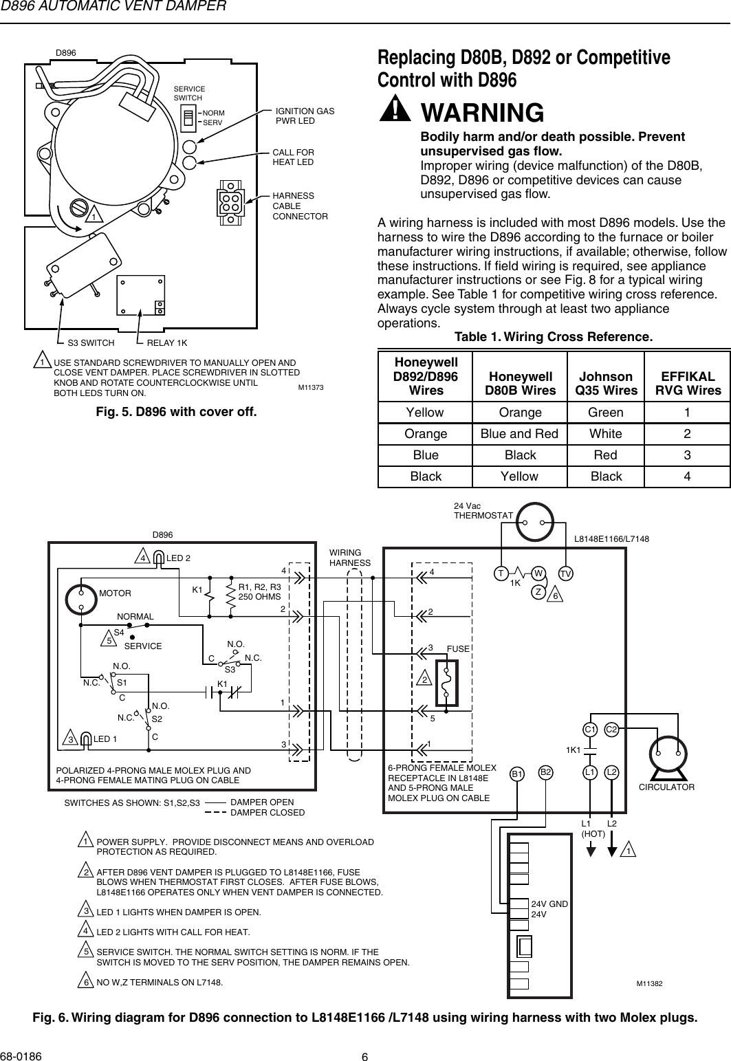
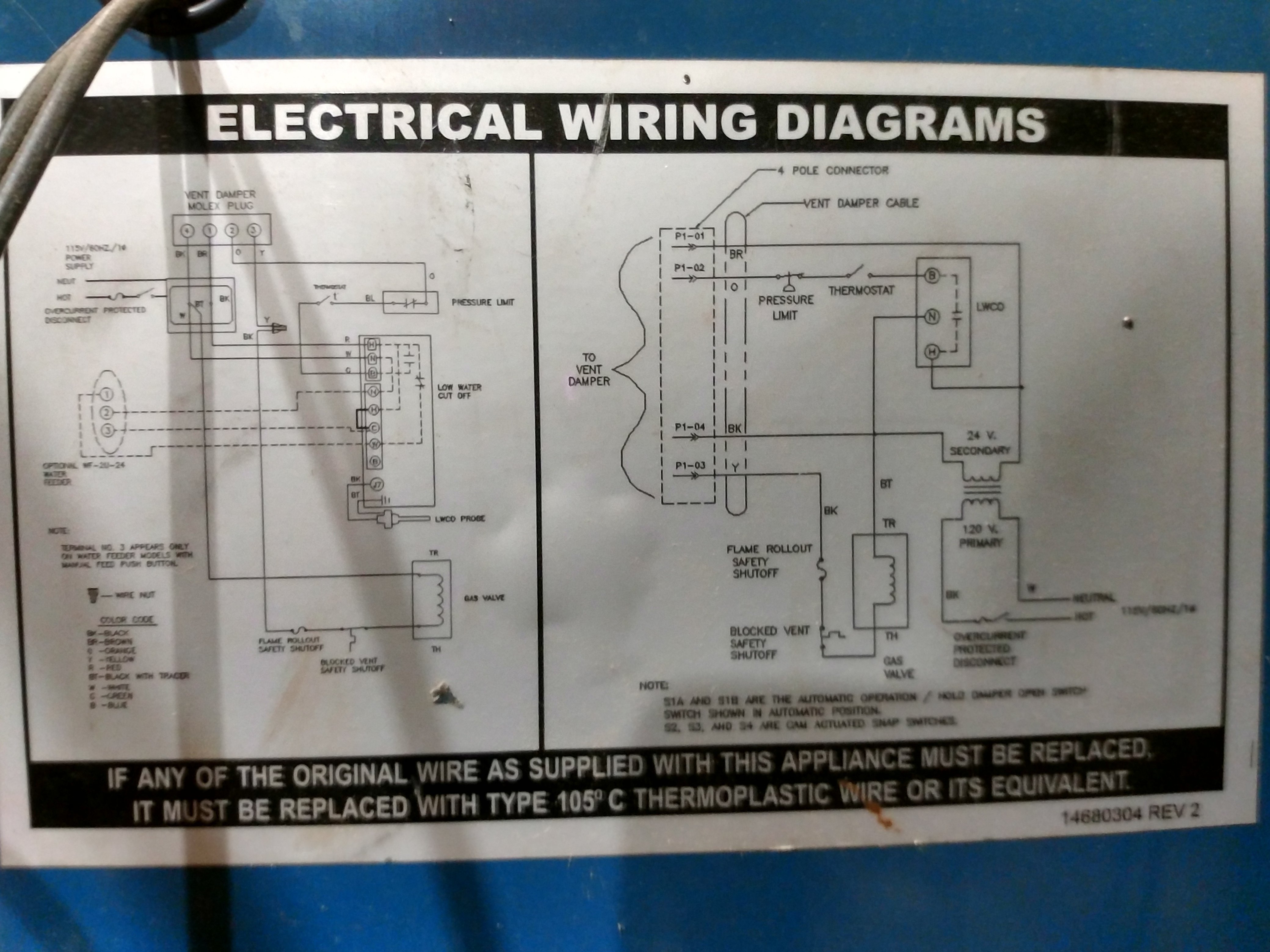
Gvd 6 wiring diagram. Gvd typical standing pilot hookup wo a redundant gas valve wiring diagram. Order the universal wire harness 46390008. Wiring diagram for model cas 3 6 and 7 chimney vent two oil fired systems with cac 120 combustion air controller. A wiring diagram is a streamlined standard photographic representation of an electrical circuit. Field controls gas vent dampers gvd are made of stainless steel and is available in 8 sizes 4 through 10 and 12. A wiring diagram is a streamlined standard photographic representation of an electrical circuit.
The fieldcontrols model gvd 6 vent damper motor to my carrier gas furnace keeps getting stuck. Dual safety switches allow the burner to fire only when the damper is in the open position. Cas 3 6 and 7 chimney vent single oil fired system with standard primary control wiring diagram. Gvd 6 wiring diagram building electrical wiring diagrams show the approximate areas and affiliations of receptacles lighting as well as irreversible electric services in a building. You know its happening by the loud buzzing sound it makes and by the fact the furnace wont kick. Gsk 3 gsk 4 gsk 250m gas spillage sensing kit installation manual.
Inspect for damage prior to the installation. Wiring diagram pics detail. The field controls gvd series gas vent damper is packaged in a single carton containing an assembled gvd instruction manual and a plug. A typical standing pilot hookup with an added gas valve is shown in diagram a. Adjoining wire paths might be revealed approximately where specific receptacles or fixtures need to get on a common circuit. Order the universal wire harness 46390008.
Installation manual and wiring diagram for gas vent damper models gvd 4 thru 12. Variety of gvd 6 wiring diagram. The gvd gas venting damper will not interfere with existing appliance safety controls when properly installed. Gvd 6 wiring diagram a thy 1 1 cd8 pmel 1 t cells were at into c57b 6 mice one day prior to inoculation with 2 5 105 b16 tumor cells in matrigel. It shows the parts of the circuit asa wiring harness is a 4 wire cable 8 feet meters long with d mating plug on one end and mating. Some oem supplied units have the wiring harness attached.
It shows the parts of the circuit as simplified shapes as well as the power as well as signal links between the tools. Inspect for damage prior to the installation. Retrofit installations require a wire harness. Retrofit installations require a wire harne ss. Some oem supplied units have the wiring harness attached.


