Dsi is wired using a dimming pair run around to each luminaire in the circuit. 05 15 mm² 33 cable types and cable cross sections solid wire with a cable cross section of 05 mm² to 15 mm².
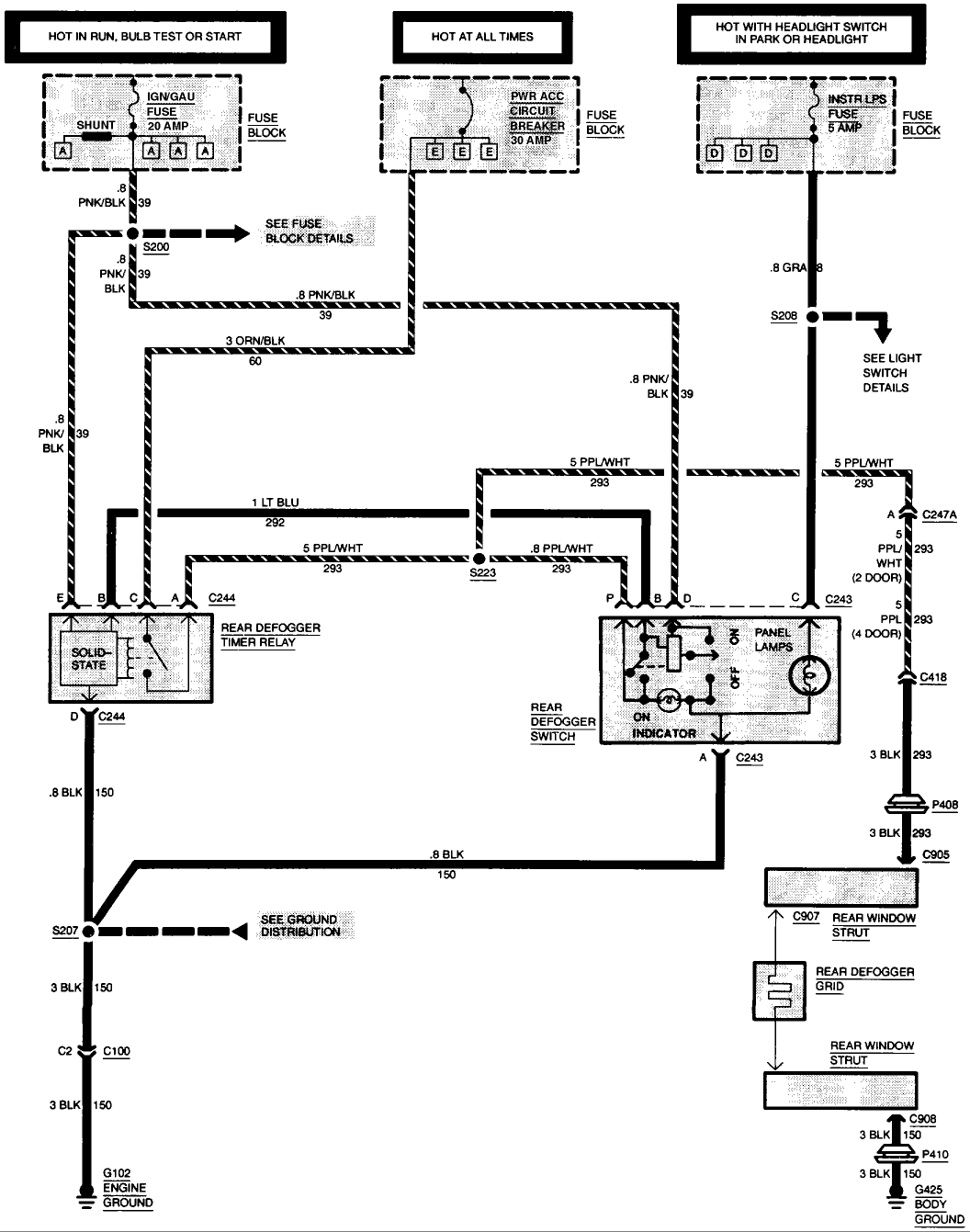
F7a Monaco Rv Dash Ac Wiring Diagram Wiring Library
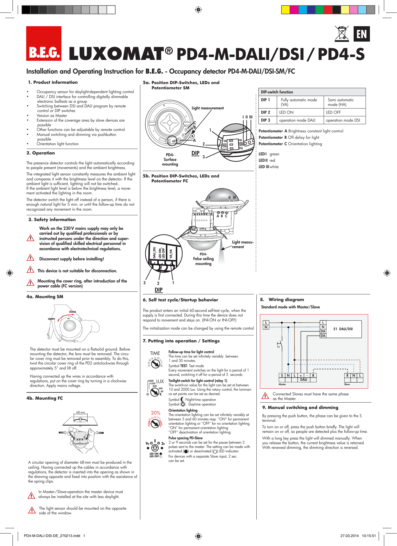
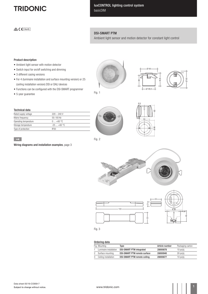
Dsi dimming wiring diagram. The installation instructions for mains voltage therefore apply. 0 10v dimming wiring diagram 0 10v dimmer switch leviton ip710 lfz or equal for other types of dimming control systems consult controls manufacturer for wiring instructions switched hot black switched hot red typical low voltage dimming wires purple gray typical electrical panel hot black typical 120v or 277v 60 hz neutral white. Dsidali 7 n l l n 32 wiring diagram for dsi smart ptm ceiling installation box 9 mm 1 wire preparation. It shows the elements of the circuit as streamlined forms and the power and signal connections between the devices. Analogue dimming is known as 1 10v dimming. Ashers fjr pin installation listed on mounted on a separate molded base for each pole rather than a common page 3 under ds circuit breaker the dsl 20o.
Installation dsidali is not selv. This dc supply can be increased or decreased by. This is because the ballast produces a 1 10v dc supply that can be increased or decreased by a potentiometer which can be either rotary or slider control. A wiring diagram is a simplified standard photographic depiction of an electric circuit. Cd see page 16 figure j2 for illustration of i similar to the ds 416 with the upper and lower stud assemblies x v. Collection of 0 10 volt dimming wiring diagram.
The ds 2065 pole unit assemhly at not included in pole unit assembly. Dimming signal is used to switch the dimming luminaire onoff and therefore the 240v feed to the luminaire fitting must come from the permanent live supply dimming ballast dimming luminaire dsi or dali luminaire non dimming circuit protection if required live neutral centre biased retractive switch 240v switching.


