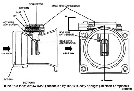
A mass airflow maf sensor. Weld the boss in place before installing the sensor.
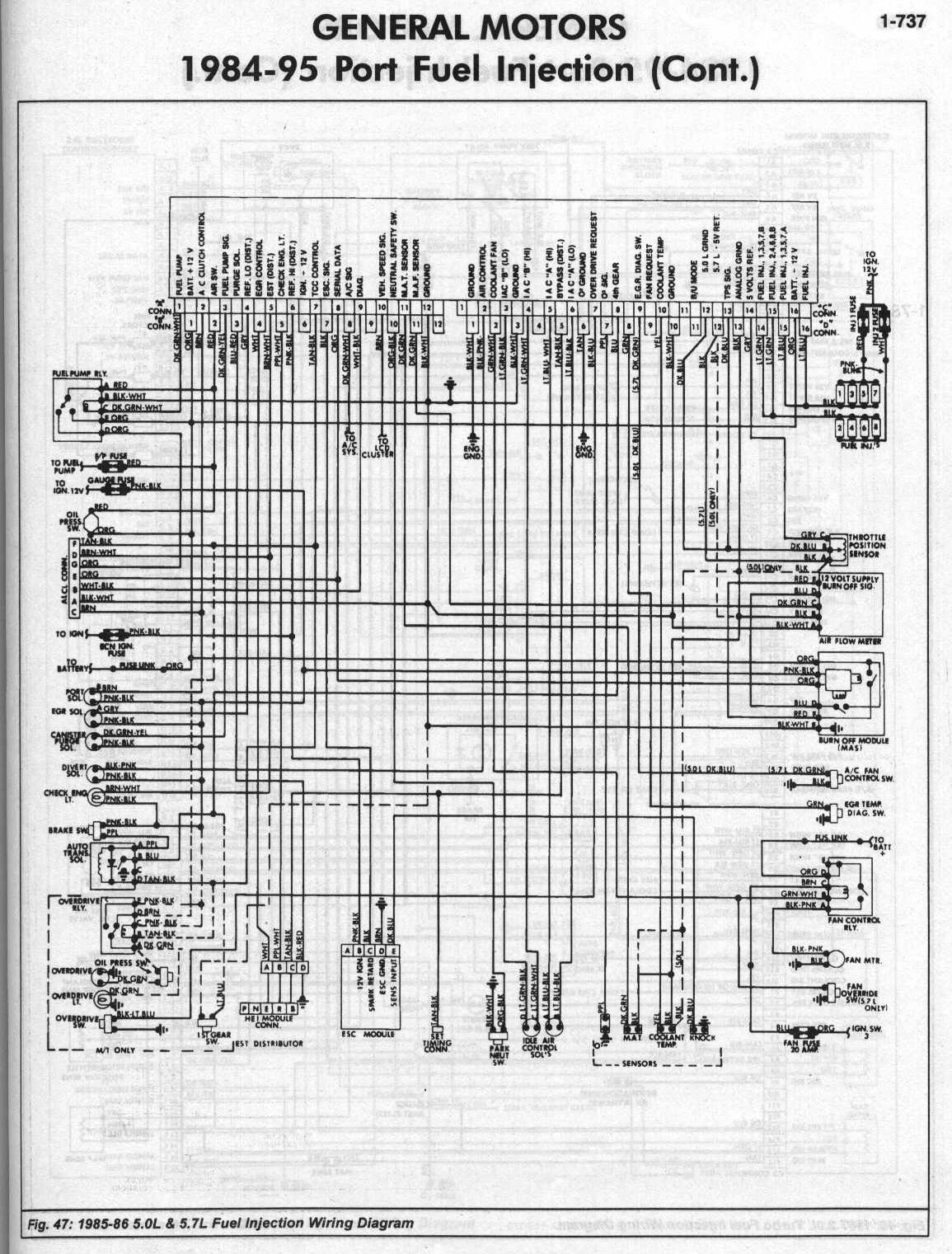
Bosch Maf Sensor Wiring Diagram General Wiring Diagram
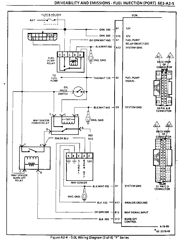
Gm maf sensor wiring diagram. Wiring specialties mass air flow sensor mafs connector 300zx mass air flow sensor wiring diagram the diagram offers visual representation of an electrical arrangement. This makes the procedure for assembling circuit simpler. Tpi maf sensor 19851989 the tpi maf sensor outputs a 05v analog signal to the ecm. A bad bosch hot wire maf sensor may be the result. The mass air flow sensors converts the amount of air drawn into the engine into a voltage signal. Late version tuned port injection tpi system without a mass airflow maf sensor designed to use.
Three wire maf sensor 19942002 the common three wire maf sensor was introduced with the 1994 lt1 vehicles. Each part ought to be placed and connected with different parts in particular way. The maf sensor must be oriented correctly in the induction system note the arrow on the sensor indicating flow direction. This signal is not compatible with the gen iii pcms. The 60102 and 60202 harness will support the mass airflow maf sensor the burn off circuit wiring and the electronic spark control esc module in addition to the other wiring common to the tuned port systems. Be sure to weld the mounting boss correctly the sensor will only mount one way in the boss see diagram.
If not the structure wont work as it ought to be. Learn how this device is connected to the ecm and vehicle electronics in general. The following schematic shows a typical circuit diagram of the mass air flow maf sensor system. The primary components of the maf sensor are thermistor a platinum hot wire and an electronic control circuit. This to me is screaming a wiring problem might not even be related to the maf wiring. Sloppy mechanics wiki gm map sensor identification map sensor wiring diagram gm map sensor identification information 1 bar 2 bar 3 bar maf sensor wiring diagrams wire harness installation instructions painless wiring a simple map maf enhancer fuelsaver mpg inc wiring and sensors megamanual wiring diagrams ertyu ls series.
Lots of possibilities and condemning the ecm is the last step in a long process. These usually could be easily recreated by lightly tapping with a small screwdriver on the maf sensor housing at idle. A noticeable stumble occurring with each tap clinches the condemnation fig. When installed in the vehicle the maf sensor should be. Certain mid 80s gm vehicles were notorious for intermittent maf sensor failures. Maf wiring diagram ford maf wiring diagram ka24de maf wiring diagram ls1 maf wiring diagram every electric arrangement is composed of various unique components.
Could be an intermittent fault in the 5v ref ground or power either to a sensor or to the ecm. It can be found in many 1996 2002 vehicles including camaro firebird corvette and gm. On the other hand this diagram is a simplified version of this arrangement. The maf or mass air flow sensor is a main input to the ecm or engine computer form air intake temperature and flow.


