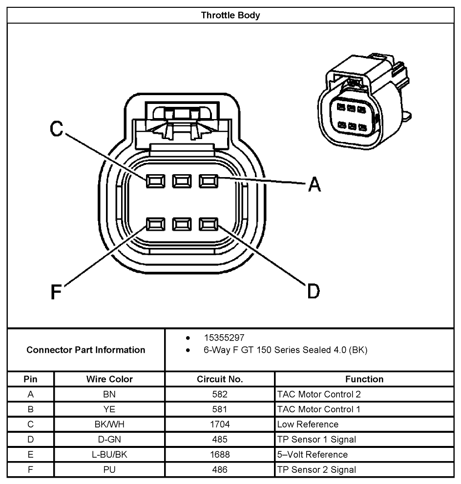
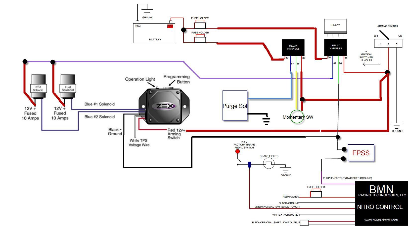
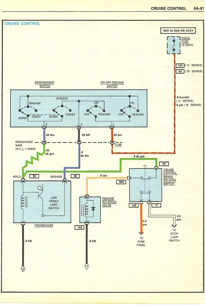
The drive by wire system first appeared on the 1997 corvette with the introduction of the ls1 engine. Gm trailer hitch wiring diagram with pin and gmc diagrams reading size.

Gm Gen Iii Ls Pcm Ecm Electronic Throttle Equipment Guide
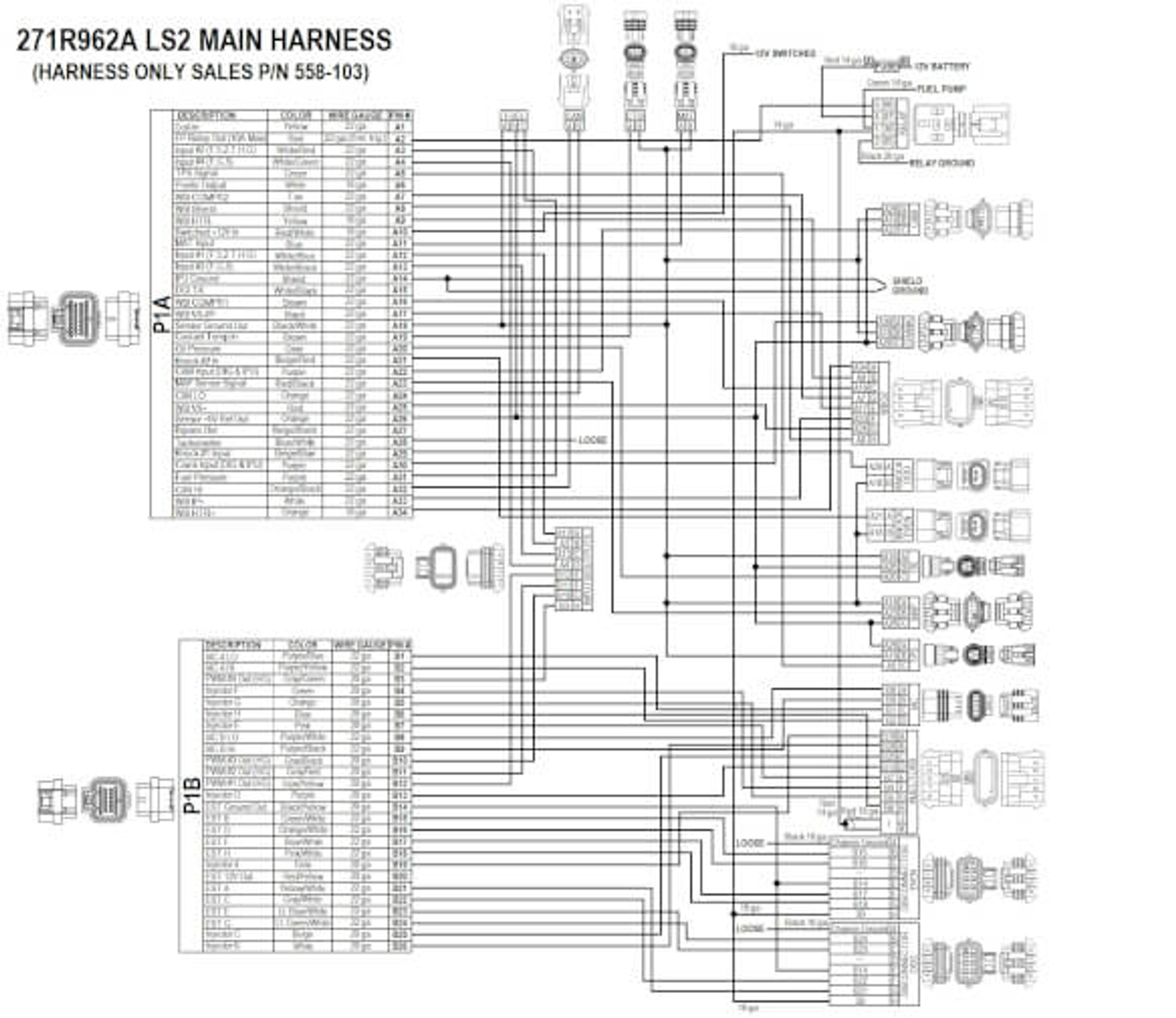
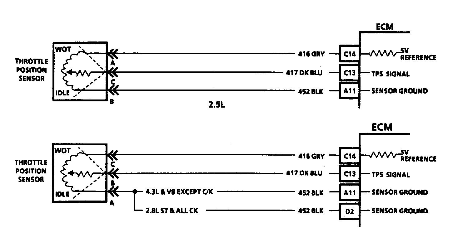
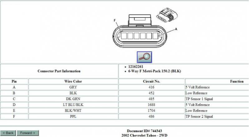
Gm dbw wiring diagram. As compared to the 19992002 gm truck tac module the 5v reference and low reference for app sensor 2 have been swapped. This wiring diagram represents the 20032004 gm truck electronic throttle control system. Everything you read about these systems indicate that they are the best thing to ever happen to automobiles. Wiring diagrams gmc. Fly by wire systems are being used in a lot of cars and pickups on the road today and one of the most common fly by wire systems in use is the one that graces most of the newer gm pickups. Gm places the vss at the.
If you run into an electrical problem with your gmc you may want to take a moment and check a few things out for yourself. Even though the f body camaro firebird was introduced with the ls1 engine and the gm truck line in 1999 with the gen iii vortec most of the trucks stayed with the throttle by cable system. 800 x 600 px source. The electronic throttle body. Next came drive by wire dbw versions that use an electronic gas pedal assembly and a servo motor mounted to the throttle body that operates the throttle plate. This system uses only two of the three app sensors.
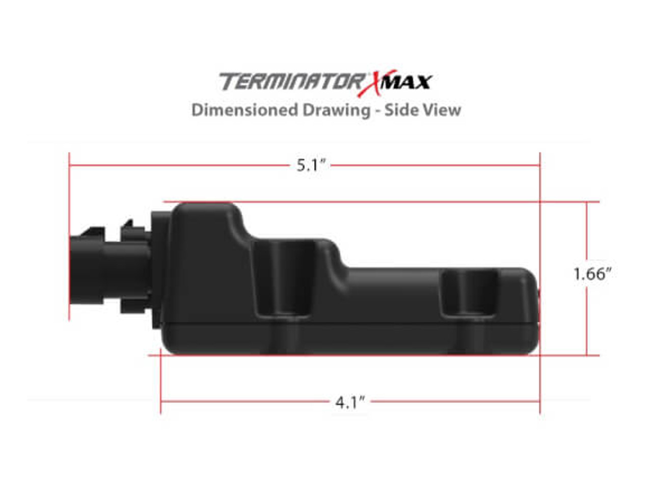
Gm pn 10379038 20 warnings. 800 x 600 px source. Use only the drive by wire wiring harness supplied by holley. Although 20032004 gm trucks use only two of the three app sensors the 2003. This harness can not be cut shortened lengthened. There are e few such as the 60l which was dbw.
Gm pn 12570790 gm pn 12580760 only the following factory drive by wire throttle pedal assemblies have been pre calibrated and approved for use with this harness. Before you dive in with a multi meter you will want to obtain a free wiring diagram for your specific modelyou may need to locate a specific color wire and its exact location.

