To reduce the risk of electrocution and or electric shock hazards. The cell must be pur chased separately.

5915a5 Amazon Com Hayward Glx Xfmr Transformer Replacement
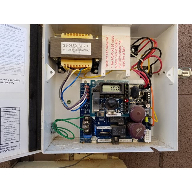
Glx pcb rite wiring diagram. To provide safe operation the aqua rite must be properly grounded and bonded. Jumpers on terminal tb1 are. Glx pcb rite verify 18 33 vdc between. Wiring diagrams for aqua rite wiring diagram glx pcb rite read1 org t 15 salt cell aqua rite turbo troubleshooting hayward for aquarite circuit board aqua rite chlorine generator aqua rite best chlorine hayward aqua rite goldencalendar co rite pump parts diagram pool wiring of deep well jet plus how to wire a hayward aquarite on 115v youtube. Only qualified technicians should remove the panel replace damaged wiring immediately insure panel is properly grounded and bonded hayward. Works with the aquarite 15k 25k and 40k gallon models.
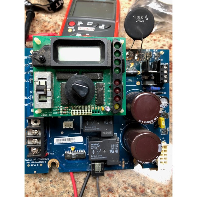
Aqua riteaqua rite xl diagnostics high voltage electrocution hazard hazardous voltage can shock burn cause serious injury and or death. Goldline main printed circuit board glx pcb rite this is the main printed circuit board for the goldline controls aquarite salt chlorine system. The aqua rite is packaged with a flow switch and cell unions. Be sure to follow local and nec electrical codes. Do you have a copy of the wiring diagram for the glx pcb main older version g1 066008j 1. If wiring is ok go to step 4b.
Control box shows lcd display but no leds are illuminated. If this is a new install or the circuit board was recently replaced verify that the board is set up to receive the correct voltage. Wiring wiring power must be shut off at the circuit breaker before performing any wiring. This is the board that typically goes bad if your unit is struck by lightning. I have a newer panel that went bad and want to go back to using an old circuit board that i already have g1 066008j 1.


-PL7100-32757102-73cf-47d9-a515-08145b1fa3c6.jpg?format=jpg&scale=both&anchor=middlecenter&autorotate=true&mode=pad&width=650&height=650)


