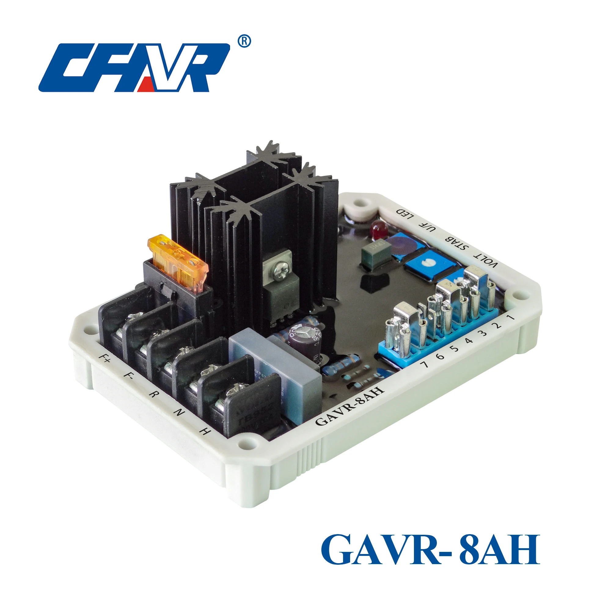
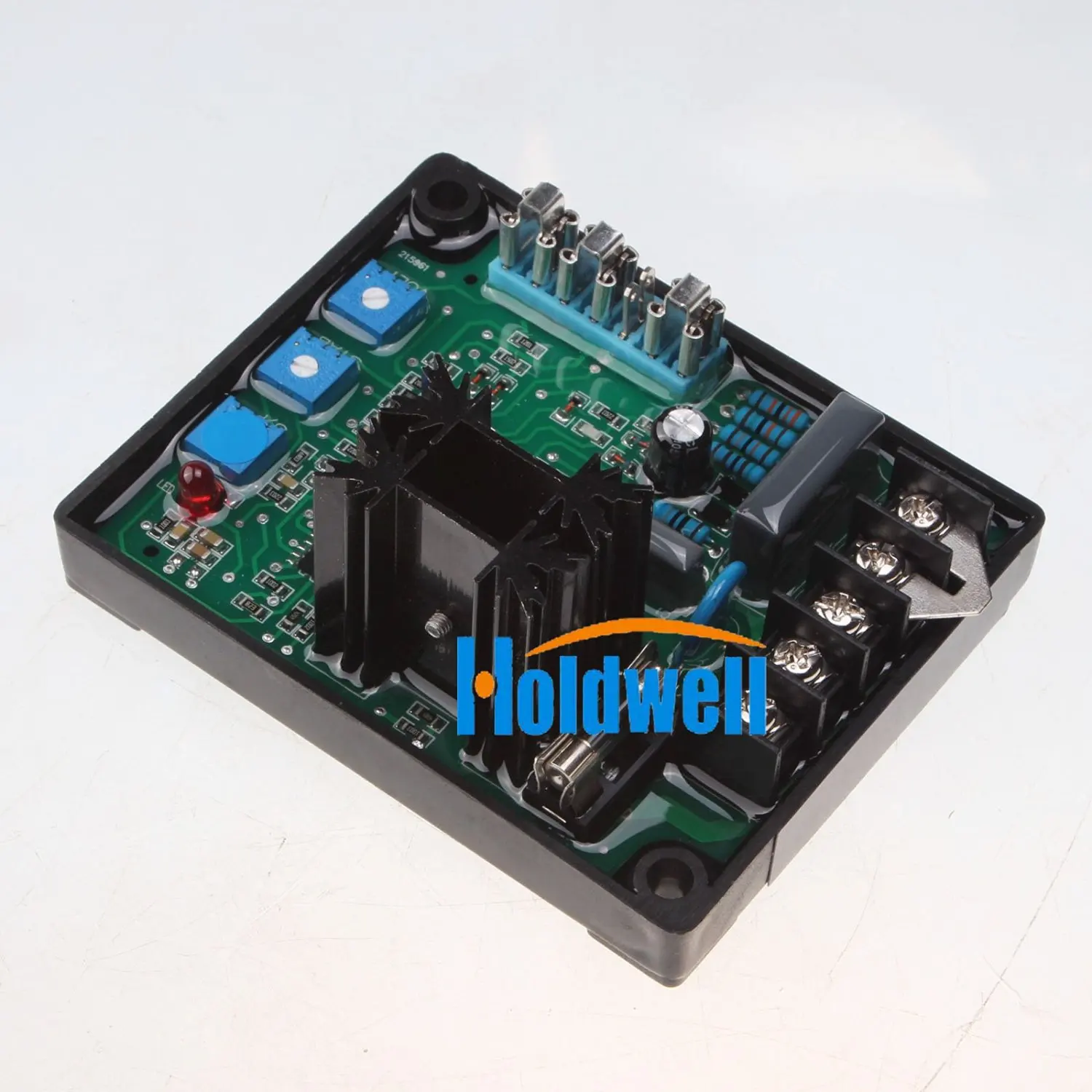
Gavr 8ah is a gavr 8a with samll size107x82x48cmsome customers specify the model number orderedthe components used in it are all imported or domestic famous brandscomplete inspection of critical electronic components to ensure high quality. Gavr 15a universal 15 amp 12 wave self excited dip switchprogrammalbe automatic voltage regulator features o5oa regulation 220400 vac programmable input rugged compact design.

Gavr 15b Voltage Regulator Dongguan Tuancheng Automation
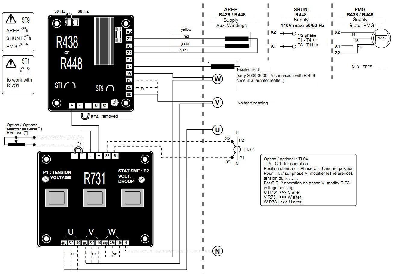
Gavr 15b wiring diagram. Publish 2019 07 23 1739 browse type gavr 15b. 15 1 in all of the wiring diagrams figs. 6264 mgb from bentley a8753aw 6467 mgb from bentley b51798 6768 mgb from bentley e1898w 6869 mgb from bentley e2333w 6870 mgb from bentley e2764w. Fender 30 schem fender 57 twin amp guitar amplifier schematic fender 59 bassman guitar amplifier schematic fender 59 bassman manual fender 63 reverb guitar amplifier schematic fender 63 reverb manual fender 63 ri vibroverb schem fender 65 deluxe reverb guitar amplifier schematic fender 65 deluxe reverb. Product summary gavr 15b voltage regulator is universal 8 amp 12 wave self excited dip switch programmable be automatic voltage regulator which is suitable for brushless generator. Gavr 20a features specifications sensinginput power input output voltage voltage voltage current resistance 220400vac1phase2wire 180240vac1phase2wire max90vdc at 240vacinput continuous 15a intermittent 20 a for 10see.
Min10 max100 voltagebuild up external volts adjustment sotf start ramp time unit power dissipation emi suppression thermaldrift. Fluke 10 11 12 service fluke 10 user fluke 17b multimeter schematics fluke 27 multimeter service manual fluke 3941b user manual fluke 51 52 thermometer service manual fluke 77 75 23 21 instruction sheet fluke 77 series 3 multimeter service manual fluke 77 series iii service manual fluke 77 series iv users. A 0804 for upflow installations a closet 32 inches wide by 30 inches deep with a 30 inch wide door is necessary. Fender diagrams schematics and service manuals download for free. Ac input terminals are for genset voltage sensing and power for avr 15. Wiring the range of sensing the phase voltage in the avr 15 is ac 110 220v.
The term makes first is shorthand for makes contact first look for example at the hook. Wiring diagrams for mgb mgc. I think you can recognize the circuit of fig. Click links for 33 different wiring diagrams for mgb and mgc large format in color. The input voltage for avr 15 is 100 240vac 5060hz. These pdf files can print full size on 11 x 17 paper.
Fluke diagrams schematics and service manuals download for free. Unitary products group 3 035 15266 003 rev. All products are 100 online powered and aging for 12 hours and the product comes out with better stability and high reliability. To retain this simple circuit appearance and represent the switch accurately i sometimes have to draw the switches upside down. Please follow the instructions and wiring diagram for the avr 15 to prevent any malfunctions.


