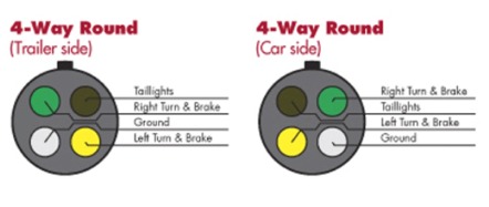
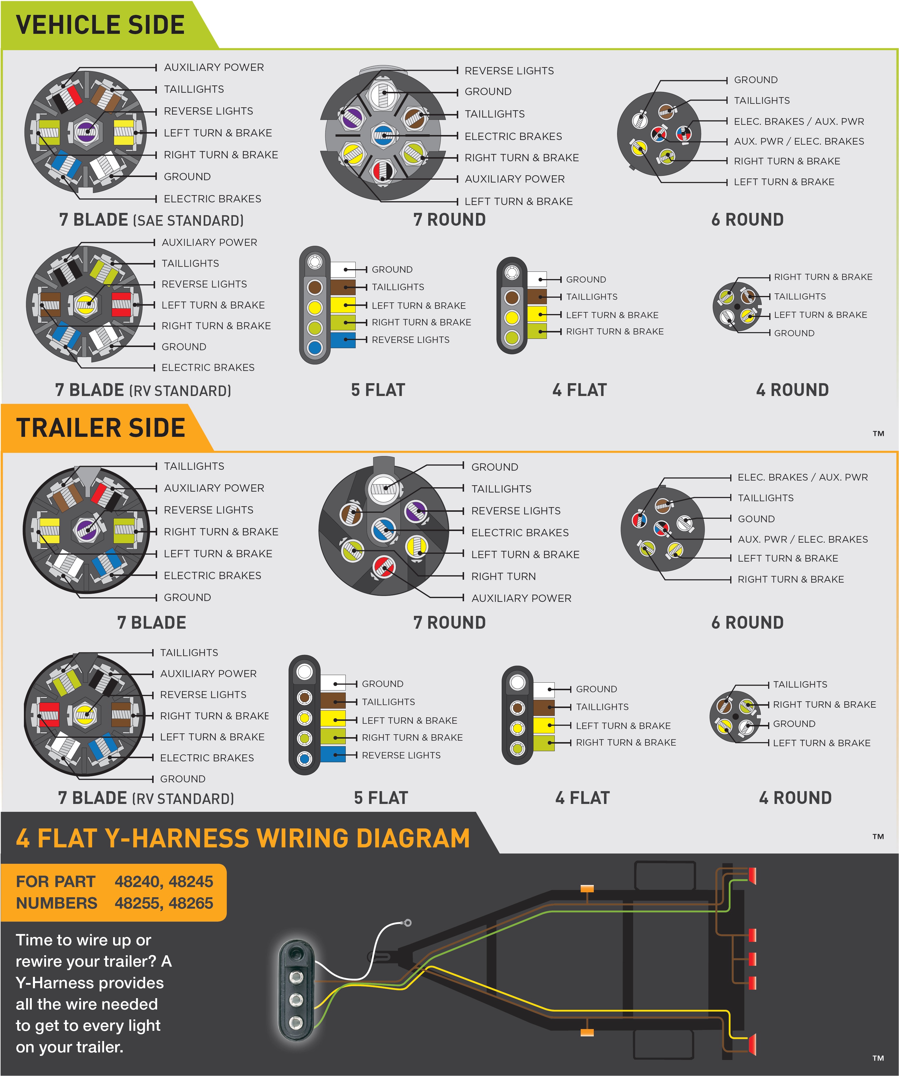
Note that this type of 4 pin connector is less common that 4 pin flat connector. They also provide a wire for a ground connection.
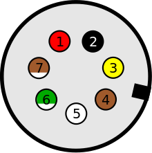
Iso Standards For Trailer Connectors Wikipedia
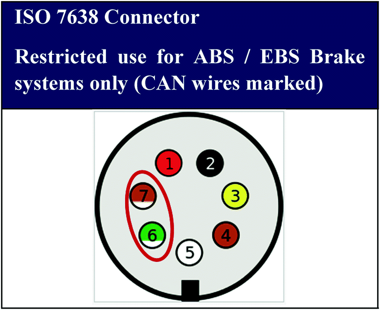
European trailer plug wiring diagram. As the name implies they use four wires to carry out the vital lighting functions. Complete with a color coded trailer wiring diagram for each plug type this guide walks through various trailer wiring installation solution including custom wiring splice in wiring and replacement wiring. Shown from inside the plug. This type of connector is normally found on utvs atvs and trailers that do not have their own braking system. Wiring us 4 pole trailer connector 2014 ford f150 to for trailer with european 7 way. 4 pin trailer wiring diagram.
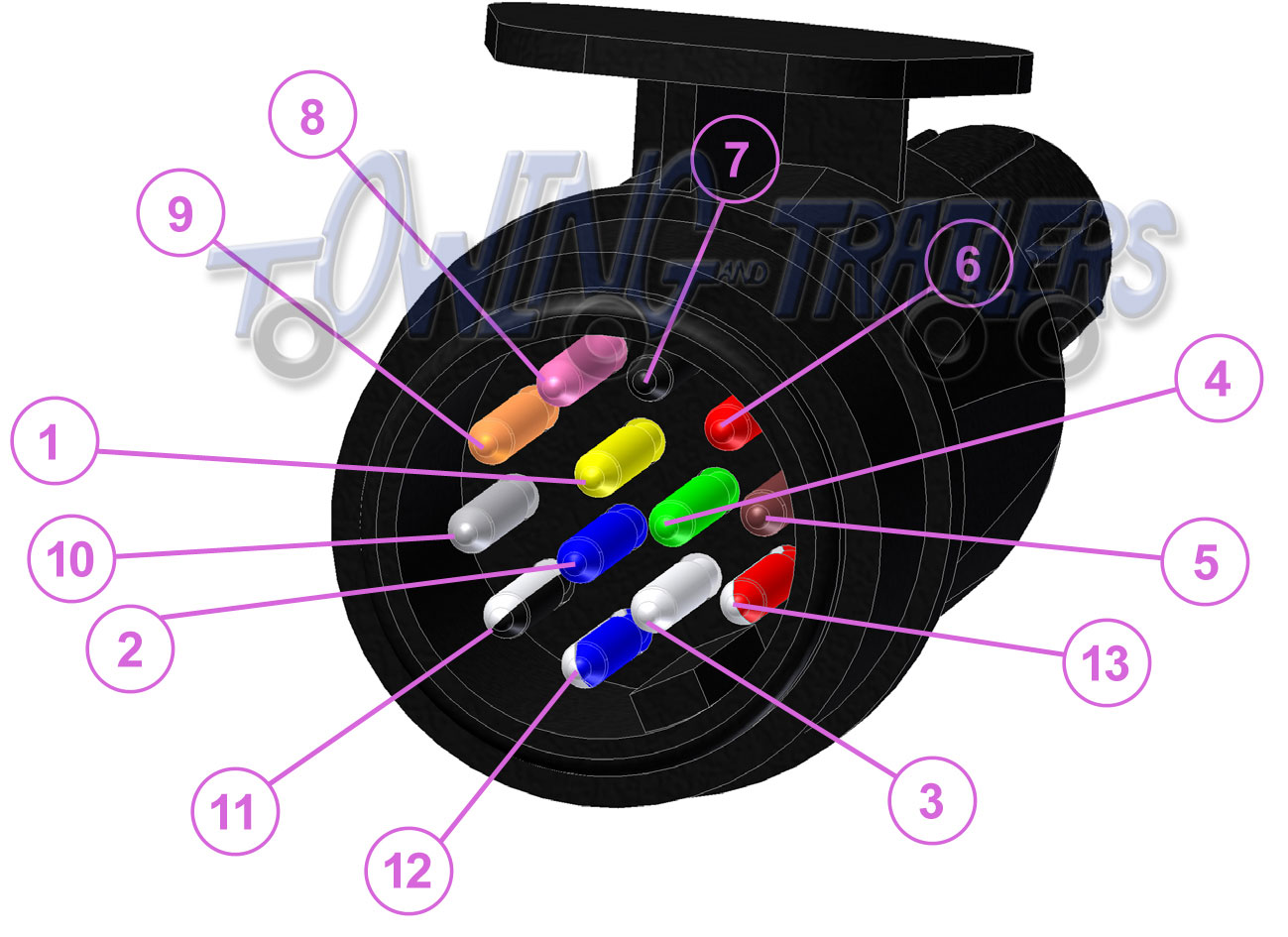
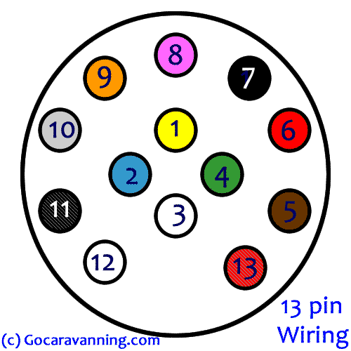
The pins usually have a small screw to retain the wire on the back. Includes guides for 7 pin 6pin 5 pin 12 pin 13 pin pin and heavy duty round plugs and sockets. Wiring diagram for a 13pin euro trailer plug. A colour coded trailer plug wiring guide to help you require your plugs and sockets. However you cannot go by wire color because it always varies from trailer to trailer. Parts needed to flat tow a 2016 ford f 150 king ranch with led tail lights behind an rv.
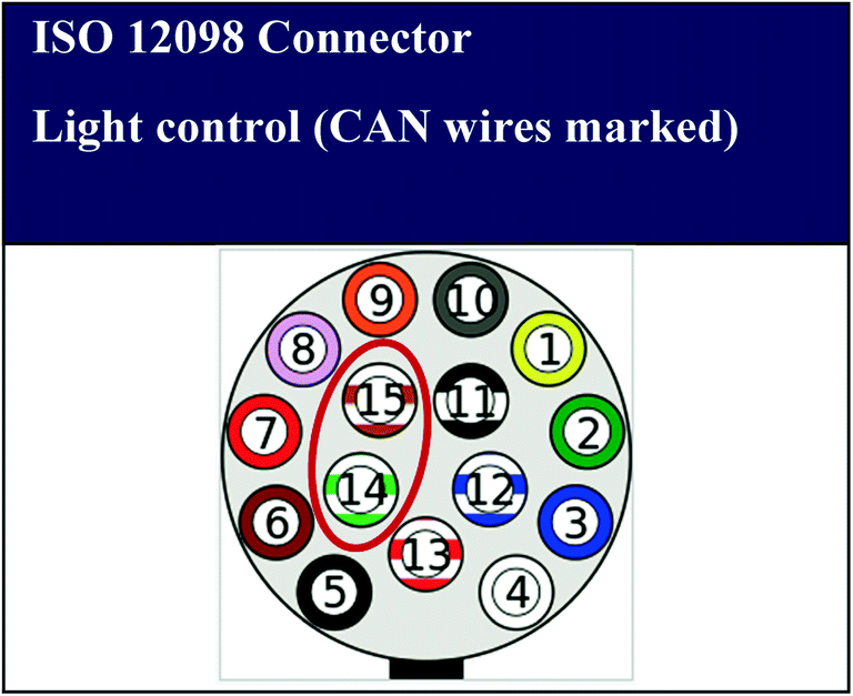
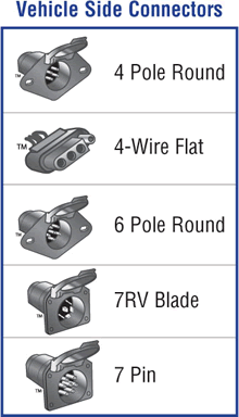
4 way trailer connectors are typically used on small trailers such as boat snowmobile utility and other trailers that that do not use brakes. The four wires control the turn signals brake lights and taillights or running lights. Can a european 7 way trailer connector be converted to a us. Below is the generic schematic of how the wiring goes. In europe both 7 pin iso 1724 and 13 pin iso 11446 are common. Below is a diagram of a 13 pin euro trailer plug with coloured pins as they are wired.
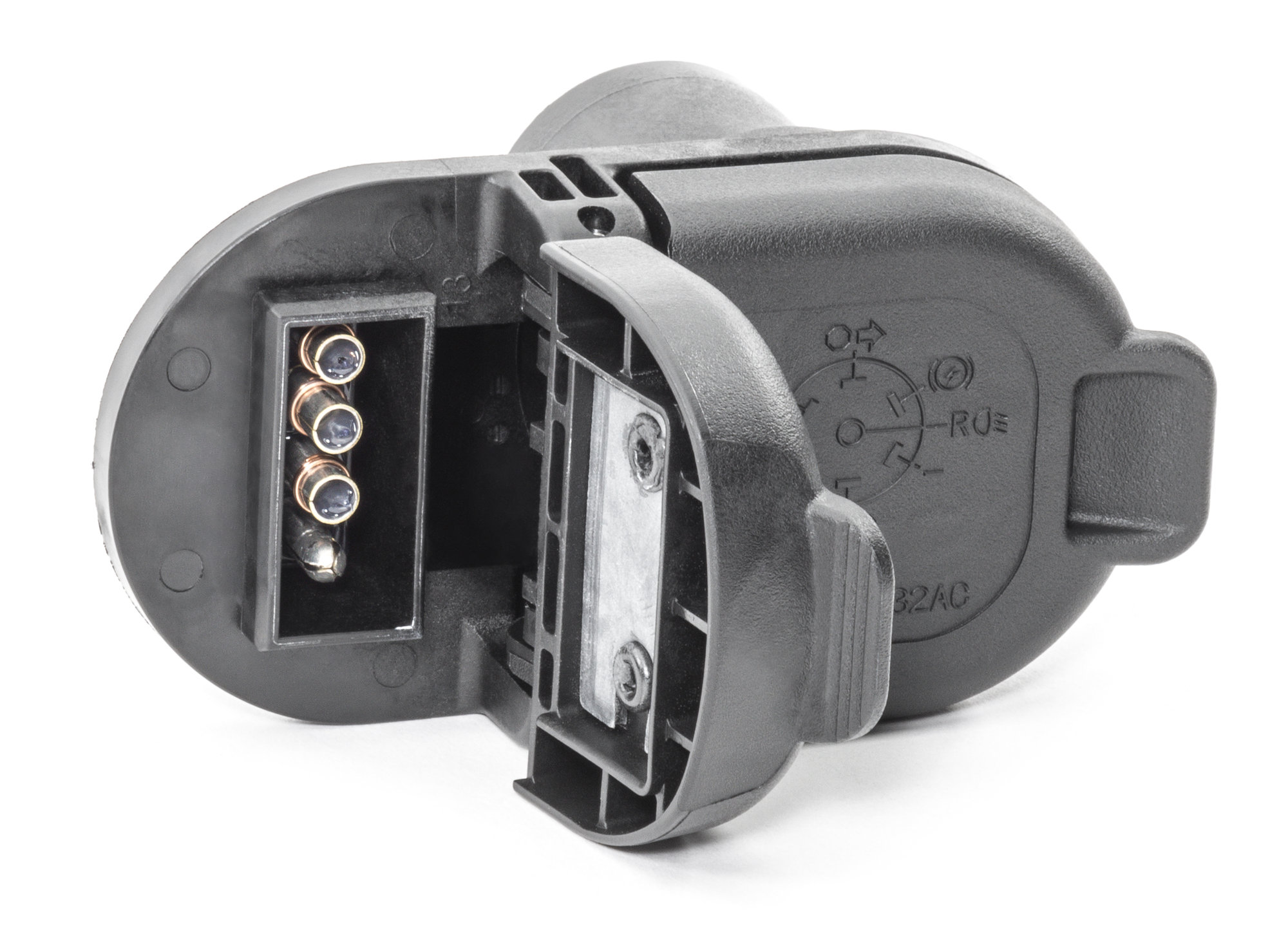
4 way trailer connectors are. If you have a european 7 way then it will be a little different. European 7 pin to us 4 way flat trailer wiring adapter for a land rover defender. You will want to trace the wire back to where it leads on the trailer to determine its function and then make the connection in the trailer connector as needed. On the rear of the pins the numbers are marked in the plastic next to each pin. 7 way plug wiring diagram standard wiring post purpose wire color tm park light green battery feed black rt right turnbrake light brown lt left turnbrake light red s trailer electric brakes blue gd ground white a accessory yellow this is the most common standard wiring scheme for rv plugs and the one used by major auto manufacturers today.
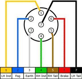
The 13 pin version being phased in is newer provides more services than the 7 pin a more positive locking and also better protection against moisture and contamination. The table and diagram below explains the connections used on a 7 pin setup. In some cases and more often in europe the trailer light will be connected using a 13 pin plug and socket. If your vehicle is not equipped with a working trailer wiring harness there are a number of different solutions to provide the perfect fit for your specific vehicle. Above we have describes the main types of trailer wiring diagrams. If you have a 13 pin socket fitted to your vehicle adaptors to plug in so you can use a normal 7 pin plug are available.
Trailer connectors between the trailer and passenger car light truck or heavy trucks with 12v systems.


