Plugs into the existing 4 way. Choose the year of your vehicle to the left to find a custom fit trailer wiring harness.
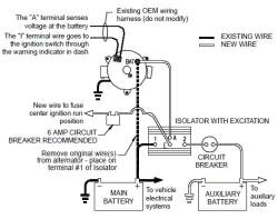
Wiring Diagram For Deka Dw08771 Battery Isolator Etrailer Com
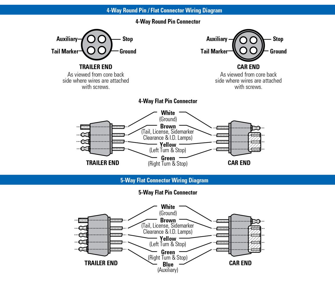
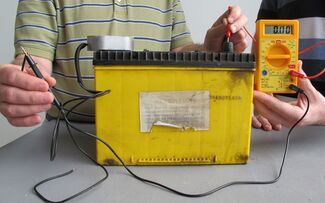
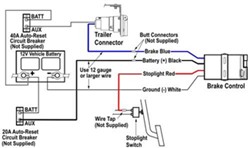
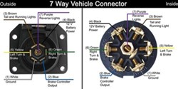
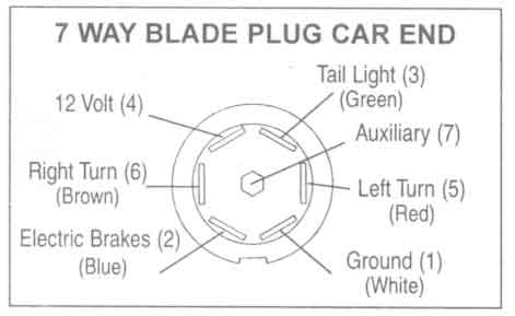
Etrailer wiring diagram. If you are looking at the inside of the trailer connector where the wires mount to the terminals starting at the top and rotating clockwise. Either approach is fine. Various connectors are available from four to seven pins that allow for the transfer of power for the lighting as well as auxiliary functions such as an electric trailer brake controller backup lights or a 12v power supply for a winch or interior trailer lights. You can use a circuit tester to verify connections. We have an excellent wiring diagram on our website i will provide you a link so you can look at it. Below is the generic schematic of how the wiring goes.
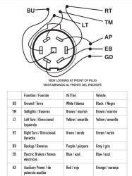
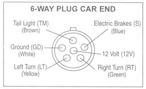
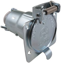
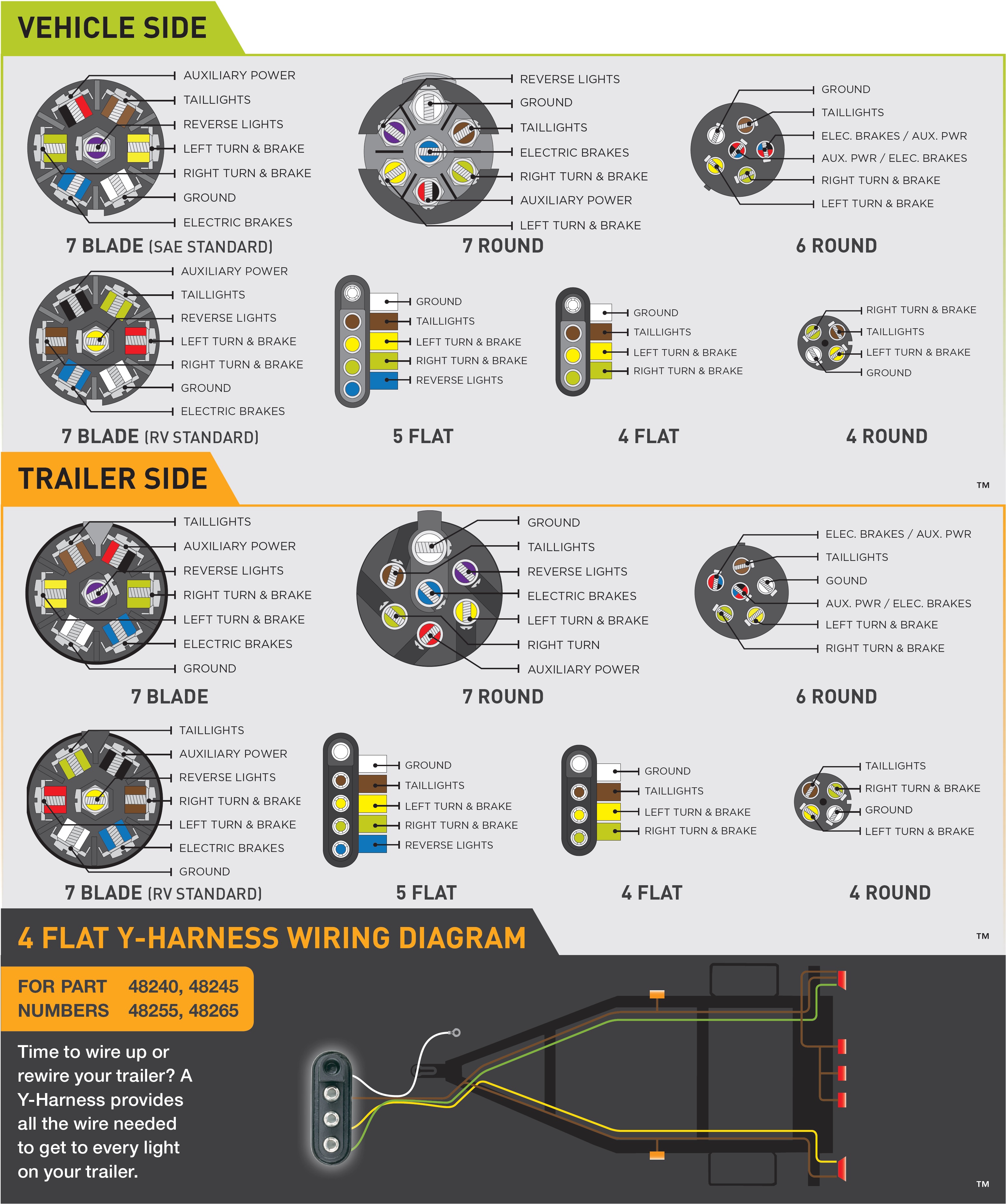
This universal wiring kit lets you install an electric brake controller sold separately in your vehicle and a 7 way connector for your trailer lights at the same time. This kit provides a 7 pole rv style trailer connector wiring harness and mounting bracket for adding an aftermarket socketwiring harness includes a 4 color coded 7 wire lead. Trailer wiring diagrams trailer wiring connectors various connectors are available from four to seven pins that allow for the transfer of power for the lighting as well as auxiliary functions such as an electric trailer brake controller backup lights or a 12v power supply for a winch or interior. Drive a crew cab extended cab with long bed cargo van or extended length suv extra wire etbcxw sold separately will make installation much easier. 4 way tow vehicle side. Trailer wiring diagram to connect the electric system of your trailer to the vehicle you will be using special connector.
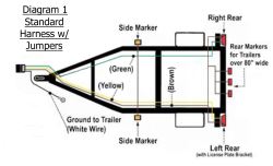
Right turn signal stop light green left turn signal stop light yellow taillight license side marker brown and a ground white. Other people suggest splitting the wires near the tongue then routing down both sides right and left specific. Gasket prevents leaks when closed has drain slot and angled design for drainage includes wiring diagram for quick installation copper plated terminal pins high conductivity and low resistance sealed. Above we have describes the main types of trailer wiring diagrams. It also helps to protect your vehicles sensitive electronics from mis wired trailers. Trailer wiring diagrams 4 way systems 4 way flat molded connectors allow basic hookup for three lighting functions.
Trailer wiring from draw tite curt pollak tow ready bosal and hopkins eliminates or reduces the need to cut and splice wires. When wiring a trailer connector it is best to wire by function as wire colors can vary. Trailer wiring diagrams trailer wiring connectors. The trailer wiring diagram above give one flavor for routing direction starting at the tongue connector then wrapping around the trailer. The below information is for reference and is commonly used throughout the industry but can vary depending on who built the trailer. Check out or trailer wiring diagrams for a quick reference on trailer wiring.
