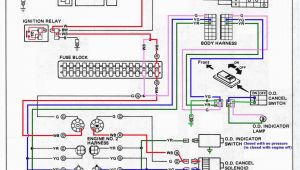
It shows the parts of the circuit as simplified shapes as well as the power and also signal links between the devices. About 6 mm from the ends of all wires that.

Cat C9 Wiring Diagram
Siga cr wiring diagram. January 9 2019 by larry a. Exposing more wire may cause a ground fault. Verify that all field wiring is free of opens shorts and ground faults. Siga cr wiring diagram a wiring diagram is a simplified traditional photographic representation of an electric circuit. A wiring diagram is a simplified standard photographic representation of an electrical circuit. Sizes 16 awg 10mm 2 and 18 awg 075mm are preferred for ease of installationsee signature loop controller catalog sheet for.
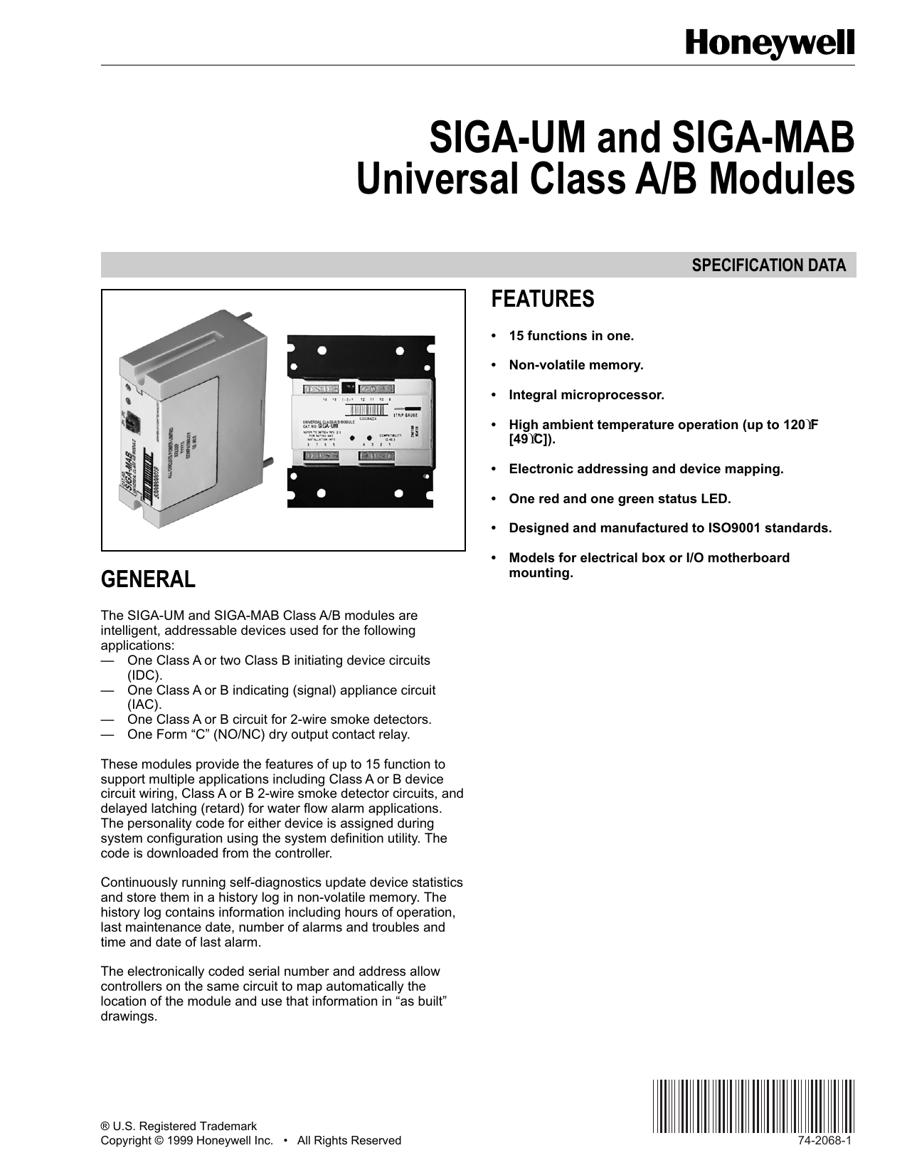
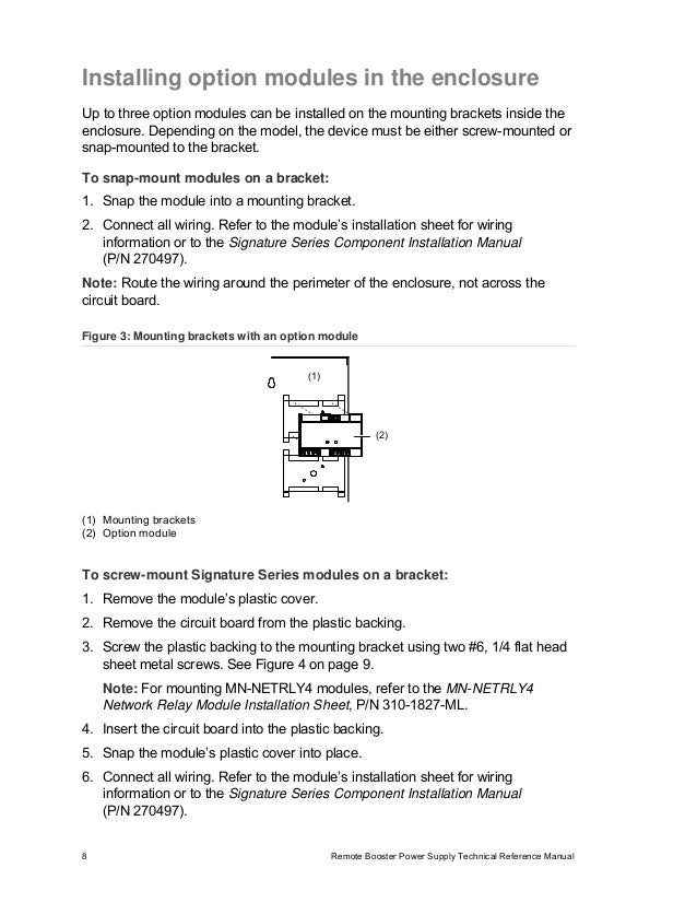
Installing the siga cr module 1 compatible electrical box 2 siga cr module 3 wall plate 4 6 32 58 machine screw 2x 5 4 12 self tapping screw wiring wire this device in accordance with applicable national and local codes ordinances and regulations. To wire the module. Connect the wires to the genesis signal master as shown siga cr gsa cr or siga cr lg must be located in the. Icons that stand for the components in the circuit and lines that represent the links between them. The siga crmcr control relay module is an intelligent motherboard eliminating direct field wiring to the module. The siga cc1 module does not supervise the riser.
Electrical wiring layouts are made up of 2 points. Data sheet 85001 0239 issue 7 not to be used for installation purposes. Compatible electrical box wall plate white 1 gang wiring. A wiring diagram is a type of schematic which makes use of abstract photographic signs to show all the interconnections of components in a system. 2 4 siga cr control relay module wire stripping guide 14 in 6 mm strip 14 in about 6 mm from the ends of all wires that connect to the terminal block of the module. It shows the elements of the circuit as simplified forms and also the power and also signal links between the tools.
Exposing less wire may result in a faulty connection. The fire alarm control panel provides this function. The control relay module model siga cr is a component of the. A wiring diagram is a form of schematic which uses abstract pictorial symbols to demonstrate every one of the interconnections of components in the system. Page 3 of 6 siga cr control relay typical wiring modules will accept 18 awg 075mm 2 16 10mm 14 awg 150mm and 12 awg 25mm2 wire sizes. Wellborn variety of siga cr wiring diagram.
Siga cr wiring diagram. Siga cr wiring diagram whats wiring diagram. Before replacing a siga cc1 module tag the wires to ensure correct reconnection.

