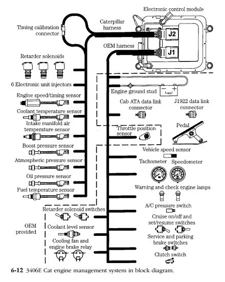
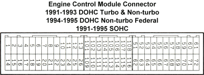
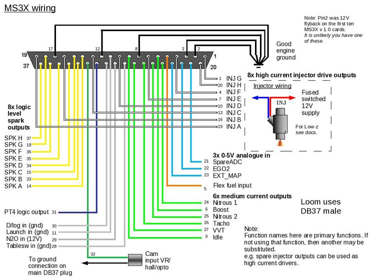
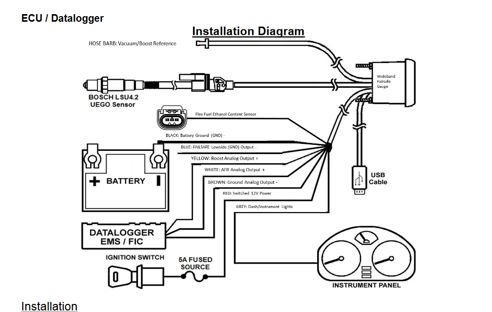
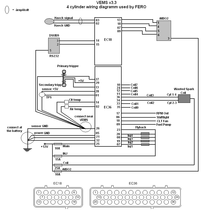
Wiring diagrams ecu connections auxiliary input connections. Please ensure all power supplies are disconnected before commencing work.
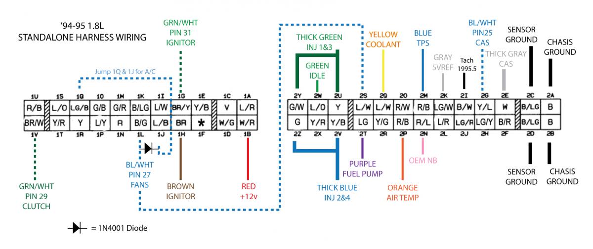
Guide For An Ems 4 With Miata Standalone Miata Turbo Forum
Ems ecu wiring diagram. With sub harness. Ecu diagrams em tech series em140160180 em7080 motorsport and stinger motorsport 886068604860 stinger v4 motorsport r tech stinger s2r dualsport dualsport v6 ecus dualsport v5 ecus q and t series ecus ignition system diagrams coil ignition systems igbt ignitors sensor diagrams 4 channel egt modulelsu 49 o2 sensorspressure sensors. Start charging wiring diagram. Custom harness for the ems stinger made specific. Ag vehicle ecu 13 ems power control 9 ah vehicle ecu 23 10 ai vehicle ecu 33 11 aj vecu and pto switches 12 am starting charging isx g with in frame 13 aq power distribution key switch 14. Link to ems north america.
Aem universal wiring harness for easily installing an ems 4 onto your racecar or powersports racing vehicle. Ag vehicle ecu 14 ems power control 9 ah vehicle ecu 24 10 ai vehicle ecu 34 11 aj vehicle ecu 44 engine brake switches 12 ak power supply manual trans start 13 al grounding options 14. Ac o f7b08 battery g01 battery s036b switch push button start a b spf7d aa0 a frc1p1 key sw crank starter ign rh oper a17 control unit vecu vehicle ecu a6 b28a14 b13 frc3e86 x2d1008 spx2d x10c1 cb2808 frc3e30 relay start cntl 1 rly36 85 86 30 87a. A 96 flying lead harness pn 30 2905 96. Load source injector arrangement. Just wondering if anyone has a wiring diagram for a ems stinger ecu for the rb30 or know where i can get one.
Wiring diagram index name description page aa power distribution frc 3. Links to generic installation wiring diagrams. This allows any kind of customizations boost evaporator purge valve als throttle kicker more ignchannels you name. Ecu setup screen describe all of the engine specific parameters in this screen. Ems illum ems batt ign illum key sw. Wiring diagram index name description page aa power distribution frc 12 3.
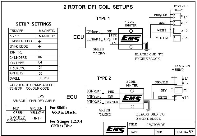
Ems stinger computer system. Wiring harness has a weatherproof connectors and color coded silk screened and bundled wires to ease installation and are pre wired for aemnet powerground can remote usb fuse and relay panel. On the ecu side they can be pressed into any ec36 position to allow logiclevel or high current drive or medium current. Ems igniter wiring nos wiring diagram 6 cylinder dfi wiring diagram 4 cylinder dfi wiring diagram 2 rotor dfi wiring diagram 3 rotor dfi wiring diagram 8. And 10 wires that can be controlled from ecu. Incorrect set up of the ecu can also lead to engine and ecu damage.
I am in the process of makin. Failure to follow all the warnings in this manual may lead to ecu and engine damage and may also void your warranty. For map installed. Ems em tech instruction manual version 20 page 1 em tech ecu manual version 20 warning.
