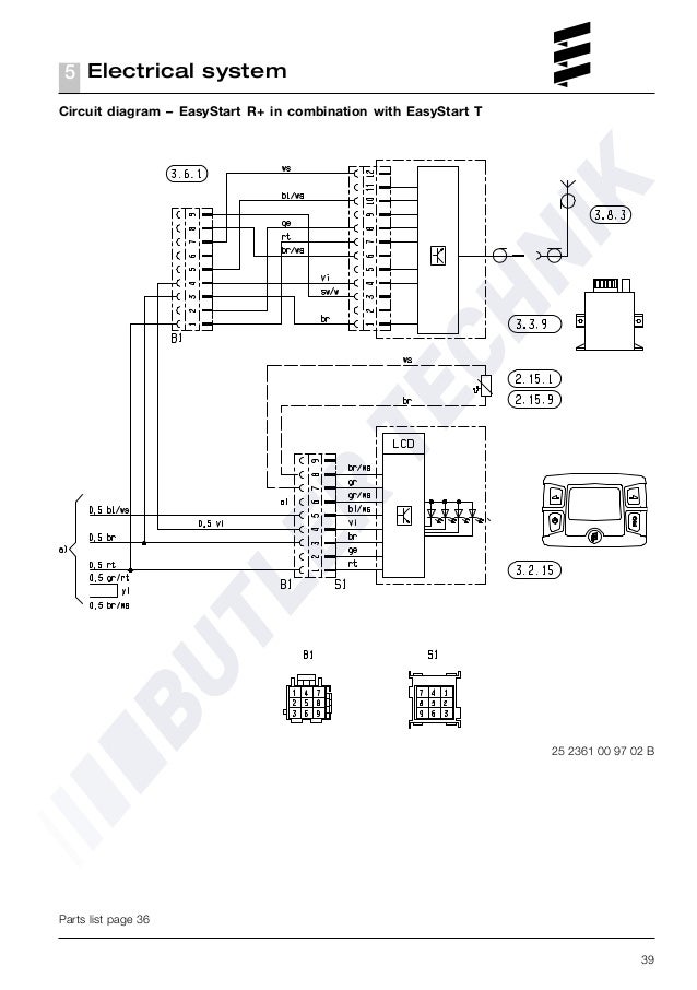
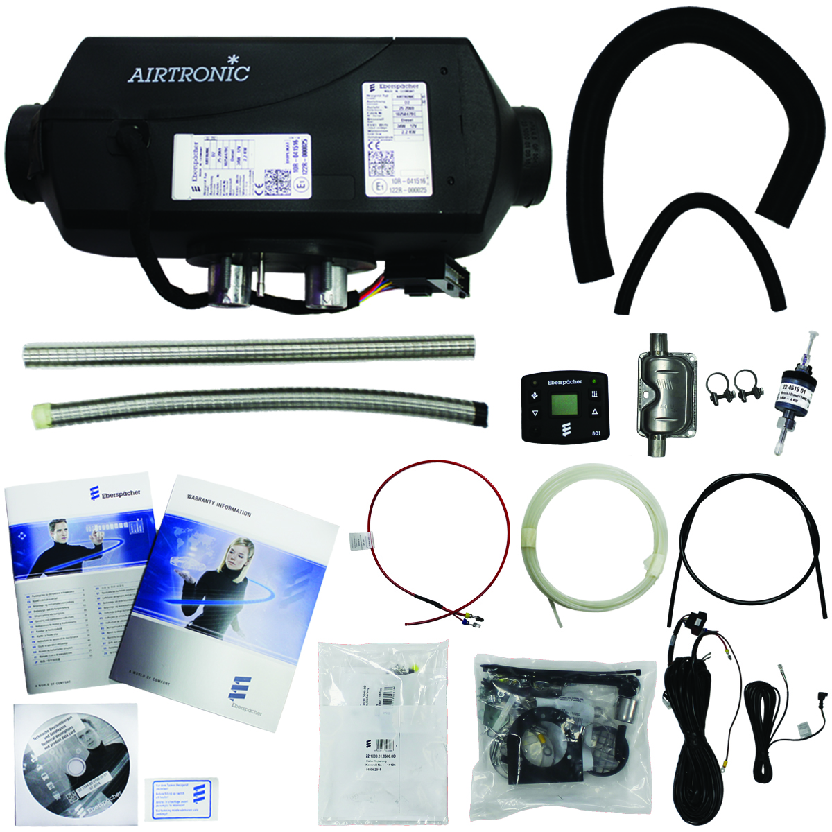
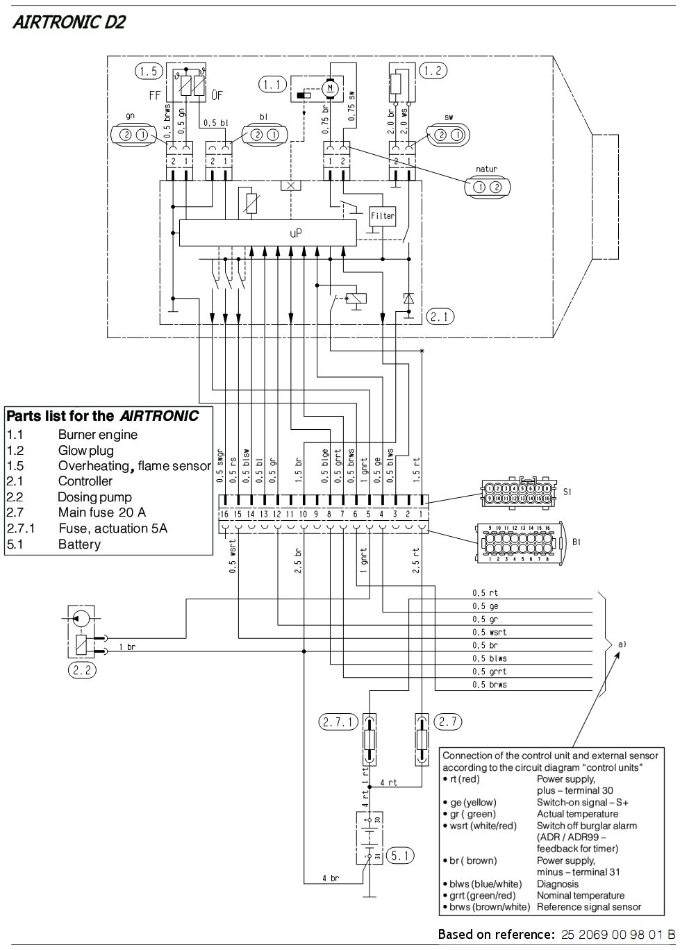
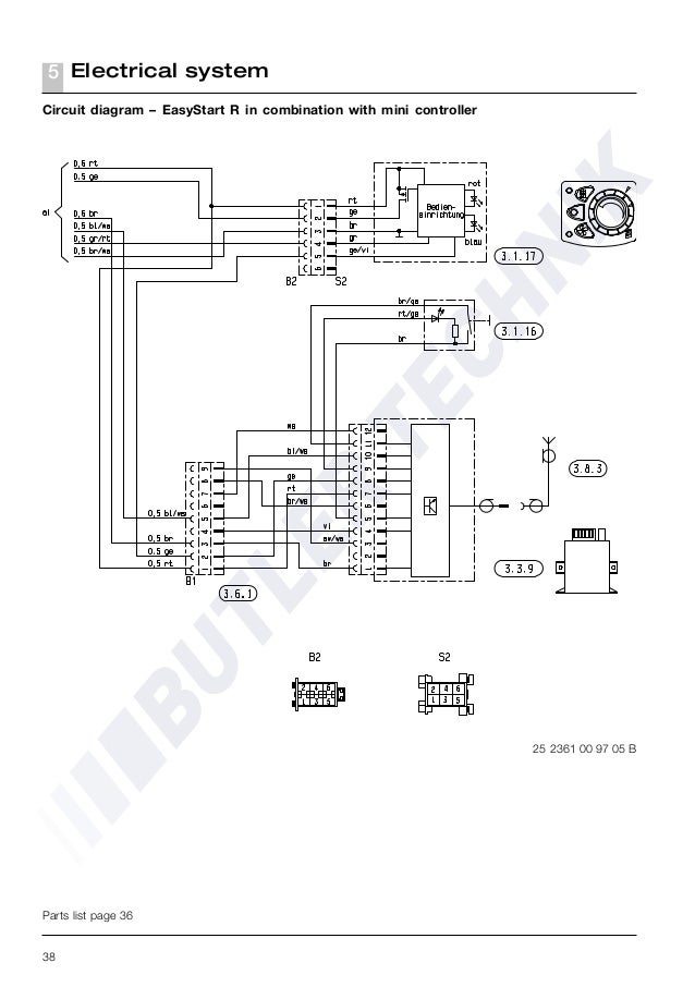
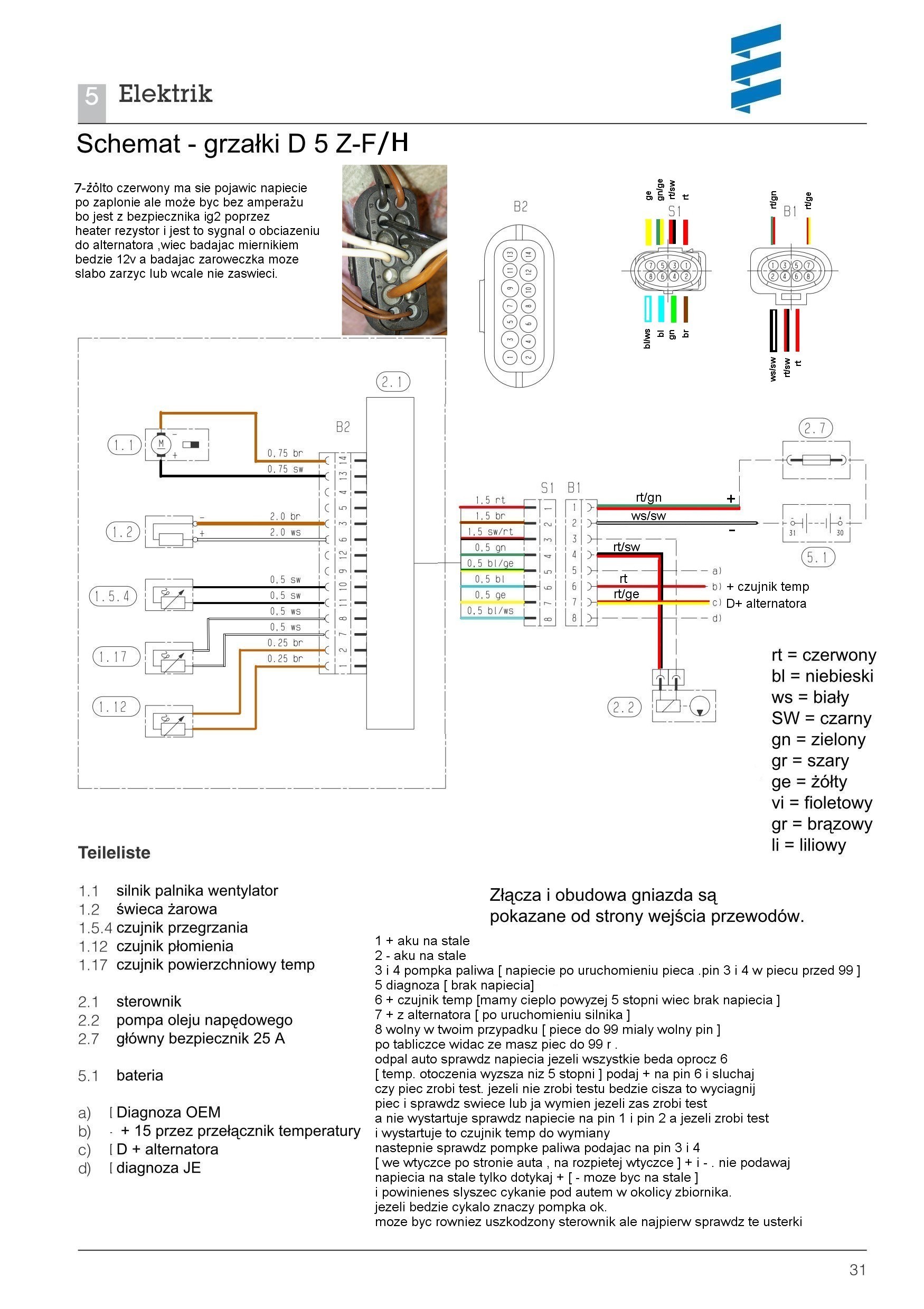
Air heater for diesel and petrol operating independently of the engine. Rt 1 ge 2 br 5 blws 6 grrt 7 brws 8 8 way housing rt 1 ge 2 5 blws 6 grrt 7 brws.
Transarctic Wiring Diagrams
Eberspacher wiring diagram. The installation manuals cover many of the details and i recommend downloading and studying the manual before starting see manuals page. Wiring diagram for control switcheseberspacher controller manual wiring diagrams find technical support manuals guides for eberspacher controllers in our online technical library. Wiring connections cause many people problems when changing or maintaining their systems. Based in ringwood hampshire eberspächer uk limited is a wholly owned subsidiary of eberspächer climate control systems gmbh of germany. Genuine eberspacher espar webasto heaters and parts. 44 1425 480151 fax.
30 off the dealer prices. Airtronic d2 12 v. Download the official eberspacher timer operating instruction manual below for useful diagrams guidance on wiring. Eberspacher airtronic d2 wiring diagram. We were established in 1977 originally to introduce diesel fuelled independent heating systems into the uk and eire for car commercial vehicle and marine markets and to create a nationwide network of dealers to provide a quick and efficient service to. Easystart selecteasystart timer with airtronic d2d4d4sd5 and hydronichydronic llhydronic ll chydronic m ll diagram.
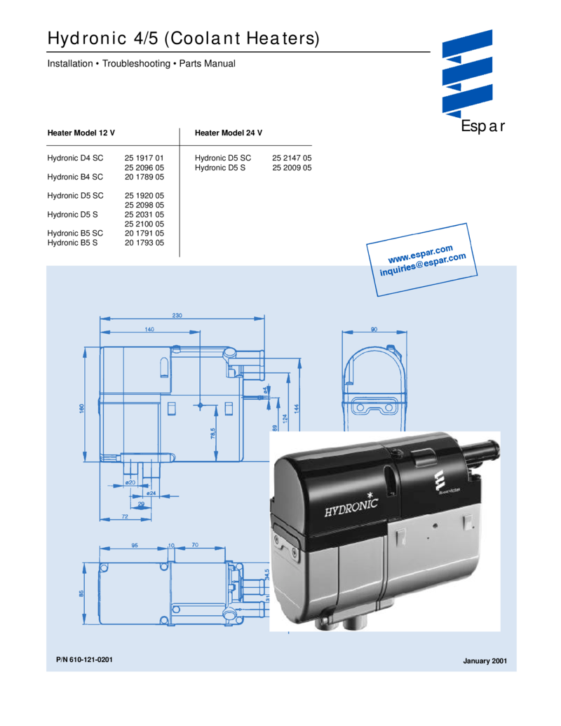
Eberspacher wiring modern air heaters airtronic d2 d4 d5 d1lcc d3lcc d1lc d3lc d5lc. Climate house yeoman road ringwood hampshire bh24 3fa phone. 25 05 00 airtronic d2 24 v. This manual is designed to be used with the hydronic d5 s and sc. Wiring diagram for control switches. Eberspacher airtronic heater webasto diesel heater eberspacher fuel pump.
Eberspächer airtronic d2 manual online. 2 diagnostic devices 4 multiple diagnostic devices are available as outlined below. Circuit diagram airtronic d2 d4 short optional loom circuit diagram airtronic d2 d4 heaters supplied with short optional loom rt 05 ge 05 gr 05 swrt 05 gnrt 10 br 10 br 05 blws 05 grrt 05 brws 05 8 way housing gr 05 br 05 319. Check operating element timer modulemini timer disconnect the plug from the operating element and bridge the red rt 05 mm² wire and the yellow ge 05 mm² wire. If no voltage is applied check the supply lead yellow ge 05 mm² wire the 5a fuse item 271 in wiring diagram on pp. 24 and 25 and the operating element.
Airtronic airtronic m technical description installation operation and maintenance instructions. Wiring diagram for control switches.

