We were established in 1977 originally to introduce diesel fuelled independent heating systems into the uk and eire for car commercial vehicle and marine markets and to create a nationwide network of dealers to provide a quick and efficient service to. This manual is designed to be used with the hydronic d5 s and sc.

Hydronic D3wz Heater English
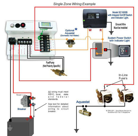
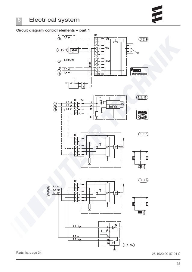
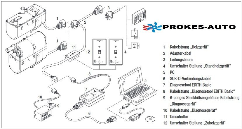
Eberspacher hydronic wiring diagram. The hydronic ii d5e diagnostics can only be accessed by using an easy start fault reader or edith. To the customer after installation of the hydronic. 44 1425 480151 fax. Please reference the data tag on your heater to verify which heater model you have. View and download eberspächer hydronic d 5 w z instruction manual online. Hydronic d 5 w z heater pdf manual download.
Climate house yeoman road ringwood hampshire bh24 3fa phone. Whether thats installation technical information eberspacher parts lists. Hydronic b 5 w z hydronic b 5 w sc hydronic b 4 w sc hydronic d 4 w sc hydronic d 5 w sc. Wiring diagrams easystart selecteasystart timer with airtronic d2d4d4sd5 and hydronichydronic llhydronic ll chydronic m ll diagram high altitude kit diagram. Based in ringwood hampshire eberspächer uk limited is a wholly owned subsidiary of eberspächer climate control systems gmbh of germany. Eberspacher d5wz wiring diagram 20102018 20102018 1 comments on eberspacher d5wz wiring diagram here youll find a range of literature to aid in maintaining your hydronic d5wz.
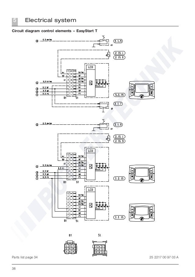
Hot in the summer before setting off separate wiring see wiring diagram pp. Eberspacher d3wz hydronic wiring diesel water heater 12v boatcampervanready to install. Engine independent water heater hydronic b 5 w s for petrol order no. Circuit diagram airtronic d2 d4 short optional loom circuit diagram airtronic d2 d4 heaters supplied with short optional loom rt 05 ge 05 gr 05 swrt 05 gnrt 10 br 10 br 05 blws 05 grrt 05 brws 05 8 way housing gr 05 br 05 319. Hydronic b 5 w s 12 v 20 1793 05 00 00 universal mounting kit 20 1777 80 00 00 hydronic b 5 w s 12 v 20 1794 05 00 00 as a complete package subject to change b 5 w s and d 5 w s technical description mounting. Wiring diagram for control switches.
The hydronic i d5 s or hydronic i d5 sc can utilize any of the fault readers. Diagnosis if the control unit detects a fault at start up of the hydronic or while the hydronic is in operation it is indicated on the timer module display within 15 seconds in the form of a fault code f 2 digit number.


