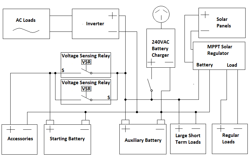
A vsr voltage sensitive relay is perfect for dual battery systems. They come in a single sense or a dual sense configuration for bi directional charging.

Extending Wiring For Motor Microskiff Dedicated To The
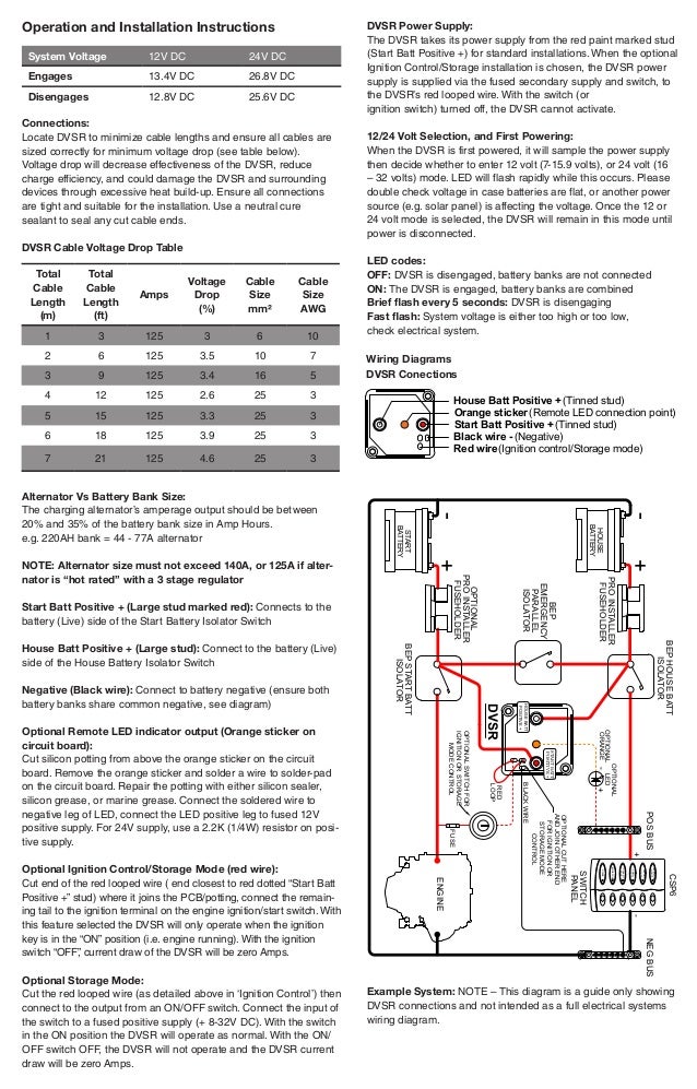
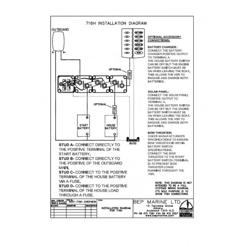
Dvsr wiring diagram. Single sense vsr. This video shows what a voltage sensitive relay or vsr is and how to install one in a dual battery setup to make sure both batteries get charged but only one can go flat. Note this diagram is a guide only showing dvsr connections and not intended as a full electrical systems wiring diagram. When the charge voltage reaches 133 volts the voltage sensitive. Bep only recommends the supplied option. Vsr dig 1224v mc compare.
Wiring diagrams dvsr conections housebatt positive startbatt positive house batt positive tinned stud start batt positive tinned stud orange wire remote led indicator output black wire negative red wire ignition controlstorage mode example system. Other options can lead to accelerated battery discharge as the sense circuit draws 00 amps continuously. It is vital to follow the wiring installation diagram which shows correct connection to the master switch. When the voltage on the charged bank rises sufficiently the dvsr engages allowing the 2nd battery bank to charge. When the engine is started the starting battery and auxiliary batteries are separated allowing only the starting battery to be charged. The output wire of the vsr should always be connected to the battery.
Dvsr cut and join jumper here for ignition or storage mode control. Any idea what would also saw a nice diagram of the wiring but you used both a vsr and an isolator. Digital voltage sensing relay dvsr 1224v 710 140a the digital voltage sensing relay dvsr allows the charging of a second battery bank from any single charging source. Single engine with two battery banks with motorized vsr part clstr bat sw 2xb mdvs sglthe digital voltage sensing relay dvsr allows the charging of a second battery bank from any single charging source. 9202011 55648 pm.


