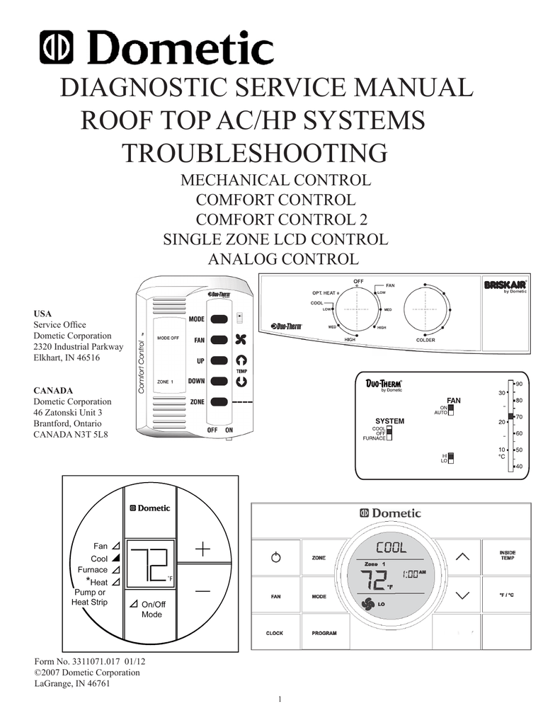
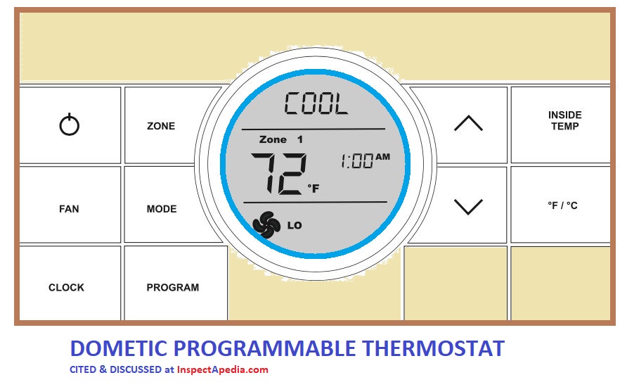
Duo therm comfort control center systems. Anyone know the wiring schematic for the dometic ccc2 multi zone kit into a dometic ac unit.
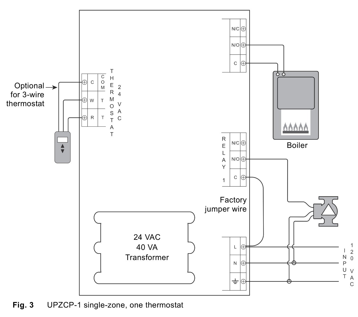
Duo Therm Comfort Control Thermostat Wiring Diagram Duo
Duo therm comfort control wiring diagram. The 2 yellow wires on a ccc2 control board are for load shedding. If not the structure wont function as it ought to be. Each component should be set and connected with other parts in specific way. I have a dometic duo therm comfort control 2 ccc2 that one dometic penguin ii and a domitec comfort control center at thermostat. Comfort control center 5. Comfort control center 4g 127 wiring 6b 28 motor 1c 34 cable assembly 4g2 128 ac power module board 4g6 130 comfort control center 4g 127 operation 1g 100 air flow obstruction 10c 38 low charge 14c 47 capillary tube blockage 14c 47.
Tm this manual has safety information and instructions to help users eliminate. Duo therm thermostat wiring diagram duo therm ac thermostat wiring diagram duo therm analog thermostat wiring diagram duo therm comfort control thermostat wiring diagram every electrical arrangement is composed of various distinct components. Collection of duo therm thermostat wiring diagram. 13082018 13082018 7 comments on duo therm 630515321 wiring diagram duo therm comfort control center. 3 cable assembly 5. 2 ac power module board 514 a comfort control center 5.
A wiring diagram is a streamlined standard photographic depiction of an electrical circuit. It shows the parts of the circuit as streamlined forms and also the power and also signal links between the tools. 1 wiring 33 motor 5. Duo thermfi comfort control center systems symptom cause refer to step this program will address the most common system problems associated with the duo therm comfort control. 1 operation 1 cold control 510 air.


